Preparations
This chapter contains informations about the course material, the required hardware and an installation guide.
Required Hardware
- nRF52840 Development Kit (DK)
- nRF52840 Dongle
- 2 micro-USB cables
- ❗️ make sure you're using micro usb cables which can transmit data (some are charging-only; these are not suitable for our workshop)
- 2 available USB-A ports on your laptop / PC (you can use a USB hub if you don't have enough ports)
In this workshop we'll use both the nRF52840 Development Kit (DK) and the nRF52840 Dongle. We'll mainly develop programs for the DK and use the Dongle to assist with some exercises.
For the span of this workshop keep the nRF52840 DK connected to your PC using a micro-USB cable. Connect the USB cable to the J2 port on the nRF52840 DK. Instructions to identify the USB ports on the nRF52840 board can be found in the top level README file.
Starter code
Project templates and starter code for this workshop can be found at https://github.com/ferrous-systems/embedded-trainings-2020
Required Software
Please install the required software before the course starts.
Course Material
This book contains the material for the beginner and the advanced workshop in embedded Rust. It aims to be as inclusive as possible. This means, that some information is available in several forms, for example pictures and text description. We also use icons so that different kinds of information are visually distiguishable on the first glance. If you have accessibility needs that are not covered, please let us know.
Icons and Formatting we use
We use Icons to mark different kinds of information in the book:
- ✅ Call for action
- ❗️ Warnings, Details that require special attention
- 🔎 Knowledge, that gets you deeper into the subject, but you do not have to understand it completely to proceed.
- 💬 Descriptions for Accessibility
Note: Notes like this one contain helpful information
Checking the Hardware
nRF52840 Dongle
Connect the Dongle to your PC/laptop. Its red LED should start oscillating in intensity. The device will also show up as:
Windows: a USB Serial Device (COM port) in the Device Manager under the Ports section
Linux: a USB device under lsusb. The device will have a VID of 0x1915 and a PID of 0x521f -- the 0x prefix will be omitted in the output of lsusb:
$ lsusb
(..)
Bus 001 Device 023: ID 1915:521f Nordic Semiconductor ASA 4-Port USB 2.0 Hub
The device will also show up in the /dev directory as a ttyACM device:
$ ls /dev/ttyACM*
/dev/ttyACM0
macOS: a usb device when executing ioreg -p IOUSB -b -n "Open DFU Bootloader". The device will have a vendor ID ("idVendor") of 6421 and a product ID ("idProduct") of 21023:
$ ioreg -p IOUSB -b -n "Open DFU Bootloader"
(...)
| +-o Open DFU Bootloader@14300000  <class AppleUSBDevice, id 0x100005d5b, registered, matched, ac$
  |     {
  |       (...)
  |       "idProduct" = 21023
  |       (...)
  |       "USB Product Name" = "Open DFU Bootloader"
  |       (...)
  |       "USB Vendor Name" = "Nordic Semiconductor"
  |       "idVendor" = 6421
  |       (...)
  |       USB Serial Number" = "CA1781C8A1EE"
  |       (...)
  |     }
  |
The device will show up in the /dev directory as tty.usbmodem<USB Serial Number>:
$ ls /dev/tty.usbmodem*
/dev/tty.usbmodemCA1781C8A1EE1
nRF52840 Development Kit (DK)
Connect one end of a micro USB cable to the USB connector J2 of the board and the other end to your PC.
💬 These directions assume you are holding the board "horizontally" with components (switches, buttons and pins) facing up. In this position, rotate the board, so that its convex shaped short side faces right. You'll find one USB connector (J2) on the left edge, another USB connector (J3) on the bottom edge and 4 buttons on the bottom right corner.
After connecting the DK to your PC/laptop it will show up as:
Windows: a removable USB flash drive (named JLINK) and also as a USB Serial Device (COM port) in the Device Manager under the Ports section
Linux: a USB device under lsusb. The device will have a VID of 0x1366 and a PID of 0x10?? or 0x01?? (? is a hex digit) -- the 0x prefix will be omitted in the output of lsusb:
$ lsusb
(..)
Bus 001 Device 014: ID 1366:1015 SEGGER 4-Port USB 2.0 Hub
The device will also show up in the /dev directory as a ttyACM device:
$ ls /dev/ttyACM*
/dev/ttyACM0
macOS: a removable USB flash drive (named JLINK) in Finder and also a USB device named "J-Link" when executing ioreg -p IOUSB -b -n "J-Link".
$ ioreg -p IOUSB -b -n "J-Link"
(...)
  | +-o J-Link@14300000  <class AppleUSBDevice, id 0x10000606a, registered, matched, active, busy 0 $
  |     {
  |       (...)
  |       "idProduct" = 4117
  |       (...)
  |       "USB Product Name" = "J-Link"
  |       (...)
  |       "USB Vendor Name" = "SEGGER"
  |       "idVendor" = 4966
  |       (...)
  |       "USB Serial Number" = "000683420803"
  |       (...)
  |     }
  |
The device will also show up in the /dev directory as tty.usbmodem<USB Serial Number>:
$ ls /dev/tty.usbmodem*
/dev/tty.usbmodem0006834208031
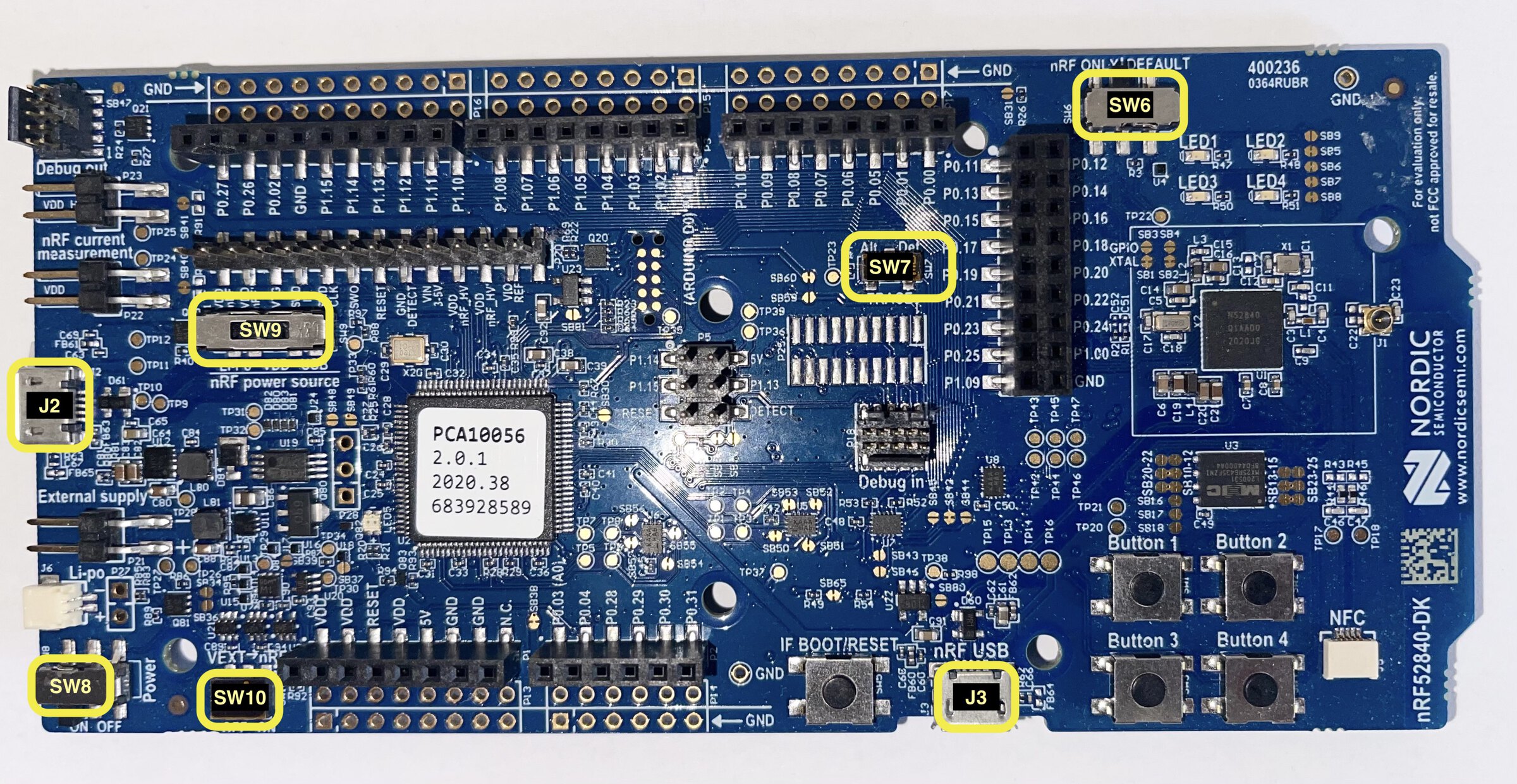
The board has several switches to configure its behavior. The out of the box configuration is the one we want. If the above instructions didn't work for you, check the position of the following switches:
- SW6 is set to the DEFAULT position (to the right - nRF = DEFAULT).
- SW7 (protected by Kapton tape) is set to the Def. position (to the right - TRACE = Def.).
- SW8 is set to the ON (to the left) position (Power = ON)
- SW9 is set to the VDD position (center - nRF power source = VDD)
- SW10 (protected by Kapton tape) is set to the OFF position (to the left - VEXT -> nRF = OFF).
For reference, here's the board picture again:
Installation Instructions
Workshop Materials
Clone and change into the workshop git repository:
$ git clone https://github.com/ferrous-systems/embedded-trainings-2020.git
$ cd embedded-trainings-2020
The workshop repository contains all workshop materials, i.e. code snippets, custom tools and the source for this handbook.
All programming will take place in its beginner/ and advanced/ subfolders.
VS Code
Windows: Go to https://code.visualstudio.com and run the installer.
Linux: Follow the instructions for your distribution on https://code.visualstudio.com/docs/setup/linux.
macOS: Go to https://code.visualstudio.com and click on "Download for Mac"
OS specific dependencies
Linux only: USB
Some of our tools depend on pkg-config and libudev.pc. Ensure you have the proper packages installed; on Debian based distributions you can use:
$ sudo apt-get install libudev-dev libusb-1.0-0-dev
To access the USB devices as a non-root user, follow these steps:
- (Optional) Connect the dongle and check its permissions with these commands:
$ lsusb -d 1915:521f
Bus 001 Device 016: ID 1915:521f Nordic Semiconductor ASA USB Billboard
$ #   ^         ^^

$ # take note of the bus and device numbers that appear for you when run the next command
$ ls -l /dev/bus/usb/001/016
crw-rw-r-- 1 root root 189, 15 May 20 12:00 /dev/bus/usb/001/016
The root root part in crw-rw-r-- 1 root root indicates the device can only be accessed by the root user.
- Create the following file with the displayed contents. You'll need root permissions to create the file.
$ cat /etc/udev/rules.d/50-oxidize-global.rules
# udev rules to allow access to USB devices as a non-root user

# nRF52840 Dongle in bootloader mode
ATTRS{idVendor}=="1915", ATTRS{idProduct}=="521f", TAG+="uaccess"

# nRF52840 Dongle applications
ATTRS{idVendor}=="2020", TAG+="uaccess"

# nRF52840 Development Kit
ATTRS{idVendor}=="1366", ENV{ID_MM_DEVICE_IGNORE}="1", TAG+="uaccess"
- Run the following command to make the new udev rules effective
$ sudo udevadm control --reload-rules
- (Optional) Disconnect and reconnect the dongle. Then check its permissions again.
$ lsusb
Bus 001 Device 017: ID 1915:521f Nordic Semiconductor ASA 4-Port USB 2.0 Hub

$ ls -l /dev/bus/usb/001/017
crw-rw-r--+ 1 root root 189, 16 May 20 12:11 /dev/bus/usb/001/017
The + part in crw-rw-r--+ indicates the device can be accessed without root permissions.
Windows only: Zadig JLink driver
On Windows you'll need to associate the nRF52840 Development Kit's USB device to the WinUSB driver.
To do that connect the nRF52840 DK to your PC using micro-USB port J2 (as done before) then download and run the Zadig tool.
In Zadig's graphical user interface,
-
Select the 'List all devices' option from the Options menu at the top.
-
From the device (top) drop down menu select "BULK interface (Interface 2)"
-
Once that device is selected,
1366 1015should be displayed in the USB ID field. That's the Vendor ID - Product ID pair. -
Select 'WinUSB' as the target driver (right side)
-
Click "Install WinUSB driver". The process may take a few minutes to complete.
You do not need to do anything for the nRF52840 Dongle device.
Rust and tooling
Base Rust installation
Go to https://rustup.rs and follow the instructions.
Windows: Do install the optional components of the C++ build tools package. The installation size may take up to 2 GB of disk space.
Rust Analyzer
All: Open VS Code and look for Rust Analyzer in the marketplace (bottom icon in the left panel). Then install it.
Windows: It's OK to ignore the message about git not being installed, if you get one!
Better TOML
All: For better handling of Cargo.toml files, we recommend you install Better TOML if you're using VS Code.
Rust Cross compilation support
All: Run this command in a terminal:
$ rustup +stable target add thumbv7em-none-eabihf
ELF analysis tools
All: Run these commands in a terminal:
$ cargo install cargo-binutils

$ rustup +stable component add llvm-tools-preview
General purpose tools
Install the flip-link and probe-run tools using the following Cargo commands:
$ cargo install probe-run
(..)
Installed package `probe-run v0.3.5` (..)

$ cargo install flip-link
(..)
Installed package `flip-link v0.1.6` (..)

$ cargo install nrfdfu
(..)
Installed package `nrfdfu v0.1.3` (..)
Tooling check
Setup check
✅ Let's check that you have installed all the tools listed in the previous section.
$ cargo size --version
cargo-size 0.3.3
✅ Connect the nRF52840-DK with your computer by plugging the usb-cable into the J2 connector on the DK (the usb connector on the short side of the board).
✅ In the terminal run the following command from the begginer/apps folder. This will build and run a simple program on the DK to test the set-up.
$ cargo run --bin hello
Beginner Workbook
In this workshop you'll get familiar with:
- the structure of embedded Rust programs,
- the existing embedded Rust tooling, and
- embedded application development using a Hardware Abstraction Layer (HAL).
To put these concepts in practice you'll write applications that use the radio functionality of the nRF52840 microcontroller.
You have received two development boards for this workshop. We'll use both in the beginner workshop.
The nRF52840 Development Kit
This is the larger development board.
The board has two USB ports: J2 and J3 and an on-board J-Link programmer / debugger -- there are instructions to identify the ports in a previous section. USB port J2 is the J-Link's USB port. USB port J3 is the nRF52840's USB port. Connect the Development Kit to your computer using the J2 port.
The nRF52840 Dongle
This is the smaller development board.
The board has the form factor of a USB stick and can be directly connected to one of the USB ports of your PC / laptop. Do not connect it just yet.
The nRF52840
Both development boards have an nRF52840 microcontroller. Here are some details about it that are relevant to this workshop.
- single core ARM Cortex-M4 processor clocked at 64 MHz
- 1 MB of Flash (at address
0x0000_0000) - 256 KB of RAM (at address
0x2000_0000) - IEEE 802.15.4 and BLE (Bluetooth Low Energy) compatible radio
- USB controller (device function)
Parts of an Embedded Program
We will look at the elements that distinguish an embedded Rust program from a desktop program.
✅ Open the beginner/apps folder in VS Code.
$ # or use "File > Open Folder" in VS Code
$ code beginner/apps
✅ Then open the src/bin/hello.rs file.
In the file, you will find the following attributes:
#![no_std]
The #![no_std] attribute indicates that the program will not make use of the standard library, the std crate. Instead it will use the core library, a subset of the standard library that does not depend on an underlying operating system (OS).
#![no_main]
The #![no_main] attribute indicates that the program will use a custom entry point instead of the default fn main() { .. } one.
#[entry]
The #[entry] attribute declares the custom entry point of the program. The entry point must be a divergent function whose return type is the never type !. The function is not allowed to return; therefore the program is not allowed to terminate.
Building an Embedded Program
The default in a Cargo project is to compile for the host (native compilation). The beginner/apps project has been configured for cross compilation to the ARM Cortex-M4 architecture. This configuration can be seen in the Cargo configuration file (.cargo/config):
# .cargo/config
[build]
target = "thumbv7em-none-eabihf" # = ARM Cortex-M4
✅ Inside the folder beginner/apps, use the following command to cross compile the program to the ARM Cortex-M4 architecture.
$ cargo build --bin hello
The output of the compilation process will be an ELF (Executable and Linkable Format) file. The file will be placed in the target/thumbv7em-none-eabihf directory.
✅ Run $ file target/thumbv7em-none-eabihf/debug/hello and compare if your output is as expected.
Expected output:
$ file target/thumbv7em-none-eabihf/debug/hello
hello: ELF 32-bit LSB executable, ARM, EABI5 version 1 (SYSV), statically linked, with debug_info, not stripped
Binary Size
ELF files contain metadata like debug information so their size on disk is not a good indication of the amount of Flash the program will use once it's loaded on the target device's memory.
To display the amount of Flash the program will occupy on the target device use the cargo-size tool, which is part of the cargo-binutils package.
✅ Use the following command to print the binary's size in system V format.
$ cargo size --bin hello -- -A
Expected output: The breakdown of the program's static memory usage per linker section.
hello  :
section              size        addr
.vector_table         256         0x0
.text                9740       0x100
.rodata              4568      0x270c
.data                   8  0x20000000
.bss                 2124  0x20000008
.uninit                 0  0x20000854
🔎 More details about each linker section:
The first three sections are contiguously located in Flash memory -- Flash memory spans from address 0x0000_0000 to 0x0010_0000 (1 MB).
- The
.vector_tablesection contains the vector table, a data structure required by the Cortex-M ISA. - The
.textsection contains the instructions the program will execute. - The
.rodatasection contains constants like strings literals.
The next three sections, .data, .bss and .uninit, are located in RAM -- RAM memory spans the address range 0x2000_0000 - 0x2004_0000 (256 KB). These sections contain statically allocated variables (static variables).
Running the Program
Setting the log level
Enter the appropriate command into the terminal you're using. This will set the log level for this session.
MacOS & Linux
$ export DEFMT_LOG=warn
PowerShell
$ $Env:DEFMT_LOG = "warn"
Windows
$ set DEFMT_LOG=warn
Running the Program
✅ Open the src/bin/hello.rs file and click the "Run" button that's hovering over the main function.
Note: you will get the "Run" button if the Rust analyzer's workspace is set to the
beginner/appsfolder. This will be the case if the current folder in VS code (left side panel) is set tobeginner/apps.
If you are not using VS code, you can run the program out of your console.
Enter the command cargo run --bin hello from within the beginer/apps folder. Rust Analyzer's "Run" button is a short-cut for that command.
NOTE: If you run into an error along the lines of "Debug power request failed" retry the operation and the error should disappear.
Expected output:
$ cargo run --bin hello
    Running `probe-run --chip nRF52840_xxAA target/thumbv7em-none-eabihf/debug/hello`
(HOST) INFO  flashing program (2 pages / 16.00 KiB)
(HOST) INFO  success!
────────────────────────────────────────────────────────────────────────────────
INFO:hello -- Hello, world!
────────────────────────────────────────────────────────────────────────────────
(HOST) INFO  device halted without error
cargo run will compile the application and then invoke the probe-run tool with its argument set to the path of the output ELF file.
The probe-run tool will
- flash (load) the program on the microcontroller
- reset the microcontroller to make it execute the new program
- collect logs from the microcontroller and print them to the console
- print a backtrace of the program if the halt was due to an error.
Should you need to configure the probe-run invocation to e.g. flash a different microcontroller you can do that in the .cargo/config.toml file.
[target.thumbv7em-none-eabihf]
runner = "probe-run --chip nRF52840_xxAA" # <- add/remove/modify flags here
# ..
🔎 How does flashing work?
The flashing process consists of the PC communicating with a second microcontroller on the nRF52840 DK over USB (J2 port). This second microcontroller, named J-Link, is connected to the nRF52840 through a electrical interface known as SWD. The SWD protocol specifies procedures for reading memory, writing to memory, halting the target processor, reading the target processor registers, etc.
🔎 How does logging work?
Logging is implemented using the Real Time Transfer (RTT) protocol. Under this protocol the target device writes log messages to a ring buffer stored in RAM; the PC communicates with the J-Link to read out log messages from this ring buffer. This logging approach is non-blocking in the sense that the target device does not have to wait for physical IO (USB comm, serial interface, etc.) to complete while logging messages since they are written to memory. It is possible, however, for the target device to run out of space in its logging ring buffer; this causes old log messages to be overwritten.
Panicking
✅ Open the src/bin/panic.rs file and click the "Run" button.
This program attempts to index an array beyond its length and this results in a panic.
────────────────────────────────────────────────────────────────────────────────
ERROR panicked at 'index out of bounds: the len is 3 but the index is 3', src/bin/panic.rs:32:13
────────────────────────────────────────────────────────────────────────────────
stack backtrace:
   0: HardFaultTrampoline
      <exception entry>
   1: lib::inline::__udf
        at ./asm/inline.rs:172:5
   2: __udf
        at ./asm/lib.rs:49:17
   3: cortex_m::asm::udf
        at /Users/name/.cargo/registry/src/github.com-1ecc6299db9ec823/cortex-m-0.7.3/src/asm.rs:43:5
   4: rust_begin_unwind
        at /Users/name/.cargo/registry/src/github.com-1ecc6299db9ec823/panic-probe-0.3.0/src/lib.rs:72:9
   5: core::panicking::panic_fmt
        at /rustc/f1edd0429582dd29cccacaf50fd134b05593bd9c/library/core/src/panicking.rs:100:14
   6: core::panicking::panic_bounds_check
        at /rustc/f1edd0429582dd29cccacaf50fd134b05593bd9c/library/core/src/panicking.rs:76:5
   7: panic::bar
        at src/bin/panic.rs:32:13
   8: panic::foo
        at src/bin/panic.rs:25:5
   9: panic::__cortex_m_rt_main
        at src/bin/panic.rs:15:5
  10: main
        at src/bin/panic.rs:11:1
  11: Reset
(HOST) ERROR the program panicked
In no_std programs the behavior of panic is defined using the #[panic_handler] attribute. In the example, the panic handler is defined in the panic_log crate but we can also implement it manually:
✅ Comment out the use apps as _; import and add the following function to the example:
#![allow(unused)]
fn main() {
#[panic_handler]
fn panic(info: &core::panic::PanicInfo) -> ! {
    defmt::error!("{}", defmt::Debug2Format(info));
    asm::udf();
}
}
Now run the program again. Try changing the format string of the panic! macro.
Using a Hardware Abstraction Layer
Open the src/bin/led.rs file.
You'll see that it initializes your board using the dk crate:
#![allow(unused)]
fn main() {
    let board = dk::init().unwrap();
}
This grants you access to the board's peripherals, like its LEDs.
The dk crate / library is a Board Support Crate tailored to this workshop to make accessing the peripherals used in this workshop extra seamless.
You can find its source code at boards/dk/src/.
dk is based on the nrf52840-hal crate, which is a Hardware Abstraction Layer (HAL) over the nRF52840 Development Kit. The purpose of a HAL is to abstract away the device-specific details of the hardware, for example registers, and instead expose a higher level API more suitable for application development.
The dk::init function we have been calling in all programs initializes a few of the nRF52840 peripherals and returns a Board structure that provides access to those peripherals. We'll first look at the Leds API.
✅ Run the led program. Two of the green LEDs on the board should turn on; the other two should stay off.
NOTE this program will not terminate itself. Within VS code you need to click "Kill terminal" (garbage bin icon) in the bottom panel to terminate it.
✅ Open the documentation for the dk crate by running the following command from the beginner/apps folder:
$ cargo doc -p dk --open
✅ Check the API docs of the Led abstraction. Change the led program, so that the bottom two LEDs are turned on, and the top two are turned off.
🔎 If you want to see logs from Led API of the dk Hardware Abstraction Layer, flash the dk with the following environment variable:
$ DEFMT_LOG=trace cargo run --bin led
Among the logs you'll find the line "I/O pins have been configured for digital output". At this point the electrical pins of the nRF52840 microcontroller have been configured to drive the 4 LEDs on the board.
After the dk::init logs you'll find logs about the Led API. As the logs indicate an LED becomes active when the output of the pin is a logical zero, which is also referred as the "low" state. This "active low" configuration does not apply to all boards: it depends on how the pins have been wired to the LEDs. You should refer to the board documentation to find out which pins are connected to LEDs and whether "active low" or "active high" applies to it.
🔎 When writing your own embedded project, you can implement your own convenience layer similar to dk, or use the matching HAL crate for your board directly. Check out awesome-embedded-rust if there's a HAL crate for the board you'd like to use.
Timers and Time
Next we'll look into the time related APIs exposed by the dk HAL.
✅ Open the src/bin/blinky.rs file.
This program will blink (turn on and off) one of the LEDs on the board. The time interval between each toggle operation is one second. This wait time between consecutive operations is generated by the blocking timer.wait operation. This function call will block the program execution for the specified Duration argument.
The other time related API exposed by the dk HAL is the dk::uptime function. This function returns the time that has elapsed since the call to the dk::init function. This function is used in the program to log the time of each LED toggle operation.
✅ Try changing the Duration value passed to Timer.wait. Try values larger than one second and smaller than one second. What values of Duration make the blinking imperceptible?
❗If you set the duration to below 2ms, try removing the defmt::println! command in the loop. Too much logging will fill the logging buffer and cause the loop to slow down, resulting in the blink frequency to reduce after a while.
nRF52840 Dongle
Next, we'll look into the radio API exposed by the dk HAL. But before that we'll need to set up the nRF52840 Dongle.
From this section on, we'll use the nRF52840 Dongle in addition to the nRF52840 DK. We'll run some pre-compiled programs on the Dongle and write programs for the DK that will interact with the Dongle over a radio link.
💬 How to find the buttons on the Dongle: Put the Dongle in front of you, so that the side with the parts mounted on faces up. Rotate it, so that the narrower part of the board, the surface USB connector, faces away from you. The Dongle has two buttons. They are next to each other in the lower left corner of the Dongle. The reset button (RESET) is mounted sideways, it's square shaped button faces you. Further away from you is the round-ish user button (SW1), which faces up.
The Dongle does not contain an on-board debugger, like the DK, so we cannot use probe-rs tools to write programs into it. Instead, the Dongle's stock firmware comes with a bootloader.
When put in bootloader mode the Dongle will run a bootloader program instead of the last application that was flashed into it. This bootloader program will make the Dongle show up as a USB CDC ACM device (AKA Serial over USB device) that accepts new application images over this interface. We'll use the nrfdfu tool to communicate with the bootloader-mode Dongle and flash new images into it.
✅ Connect the Dongle to your computer. Put the Dongle in bootloader mode by pressing its reset button.
When the Dongle is in bootloader mode its red LED will pulsate. The Dongle will also appear as a USB CDC ACM device with vendor ID 0x1915 and product ID 0x521f.
You can also use our cargo xtask usb-list tool, a minimal cross-platform version of the lsusb tool, to check out the status of the Dongle.
✅ Run cargo xtask usb-list to list all USB devices; the Dongle will be highlighted in the output, along with a note if in bootloader mode.
Output should look like this:
$ cargo xtask usb-list
(..)
Bus 001 Device 016: ID 1915:521f <- nRF52840 Dongle (in bootloader mode)
🔎 cargo xtask lets us extend cargo with custom commands which are installed as you run them for the first time. We've used it to add some helper tools to our workshop materials while keeping the preparation installations as minimal as possible.
Now that the device is in bootloader mode browse to the boards/dongle directory. You'll find some ELF files (without a file ending) there. These are pre-compiled Rust programs to be flashed onto your dongle.
For the next section you'll need to flash the loopback file onto the Dongle.
✅ Run the following command:
$ nrfdfu boards/dongle/loopback
Expected output:
[INFO  nrfdfu] Sending init packet...
[INFO  nrfdfu] Sending firmware image of size 37328...
[INFO  nrfdfu] Done.
After the device has been programmed it will automatically reset and start running the new application.
🔎 Alternatively, you can also use nordic's own nrfutil tool to convert a .hex file and flash it for you, among many other things nrfutil is a very powerful tool, but also unstable at times, which is why we replaced the parts we needed from it with nrfdfu.
🔎 The loopback application will make the Dongle enumerate itself as a CDC ACM device.
✅ Run cargo xtask usb-list tool to see the newly enumerated Dongle in the output:
$ cargo xtask usb-list
(..)
Bus 001 Device 020: ID 2020:0309 <- nRF52840 Dongle (loopback.hex)
The loopback app will log messages over the USB interface. To display these messages on the host we have provided a cross-platform tool: cargo xtask serial-term.
❗ Do not use serial terminal emulators like minicom or screen. They use the USB TTY ACM interface in a slightly different manner and may result in data loss.
✅ Run cargo xtask serial-term. It shows you the logging output the Dongle is sending on its serial interface to your computer. This helps you monitor what's going on at the Dongle and debug connection issues. You should see the following output:
$ cargo xtask serial-term
deviceid=588c06af0877c8f2 channel=20 TxPower=+8dBm app=loopback.hex
This line is printed by the loopback app on boot. It contains the device ID of the dongle, a 64-bit unique identifier (so everyone will see a different number); the radio channel that the device will use to communicate; and the transmission power of the radio in dBm.
If you don't get any output from cargo xtask serial-term check the USB dongle troubleshooting section.
Interference
At this point you should not get more output from cargo xtask serial-term.
❗If you get "received N bytes" lines in output like this:
$ cargo xtask serial-term
deviceid=588c06af0877c8f2 channel=20 TxPower=+8dBm
received 7 bytes (CRC=Ok(0x2459), LQI=0)
received 5 bytes (CRC=Ok(0xdad9), LQI=0)
received 6 bytes (CRC=Ok(0x72bb), LQI=0)
That means the device is observing interference traffic, likely from 2.4 GHz WiFi or Bluetooth. In this scenario you should switch the listening channel to one where you don't observe interference. Use the cargo xtask change-channel tool to do this. The tool takes a single argument: the new listening channel which must be in the range 11-26.
$ cargo xtask change-channel 11
requested channel change to channel 11
Then you should see new output from cargo xtask serial-term:
deviceid=588c06af0877c8f2 channel=20 TxPower=+8dBm
(..)
now listening on channel 11
Leave the Dongle connected and cargo xtask serial-term running. Now we'll switch back to the Development Kit.
Radio Out
In this section you'll send radio packets from the DK to the Dongle and get familiar with the different settings of the radio API.
Radio Setup
✅ Open the src/bin/radio-send.rs file.
✅ First run the program radio-send.rs as it is. You should see new output in the output of cargo xtask serial-term.
$ cargo xtask serial-term
deviceid=588c06af0877c8f2 channel=20 TxPower=+8dBm app=loopback.hex
received 5 bytes (CRC=Ok(0xdad9), LQI=53)
The program broadcasts a radio packet that contains the 5-byte string Hello over channel 20 (which has a center frequency of 2450 MHz). The loopback program running on the Dongle is listening to all packets sent over channel 20; every time it receives a new packet it reports its length and the Link Quality Indicator (LQI) metric of the transmission over the USB/serial interface. As the name implies the LQI metric indicates how good the connection between the sender and the receiver is.
Messages
In radio-send.rs we introduce three different types for messages:
#![allow(unused)]
fn main() {
let msg: &[u8; 5] = &[72, 101, 108, 108, 111];
let msg: &[u8; 5] = &[b'H', b'e', b'l', b'l', b'o'];
let msg: &[u8; 5] = b"Hello";
}
Here, we explain the different types.
Slices
The send method takes a reference -- in Rust, a reference (&) is a non-null pointer that's compile-time known to point into valid (e.g. non-freed) memory -- to a Packet as argument. A Packet is a stack-allocated, fixed-size buffer. You can fill the Packet (buffer) with data using the copy_from_slice method -- this will overwrite previously stored data.
This copy_from_slice method takes a slice of bytes (&[u8]). A slice is a reference into a list of elements stored in contiguous memory. One way to create a slice is to take a reference to an array, a fixed-size list of elements stored in contiguous memory.
#![allow(unused)]
fn main() {
// stack allocated array
let array: [u8; 3] = [0, 1, 2];

let ref_to_array: &[u8; 3] = &array;
let slice: &[u8] = &array;
}
slice and ref_to_array are constructed in the same way but have different types. ref_to_array is represented in memory as a single pointer (1 word / 4 bytes); slice is represented as a pointer + length (2 words / 8 bytes).
Because slices track length at runtime rather than in their type they can point to chunks of memory of any length.
#![allow(unused)]
fn main() {
let array1: [u8; 3] = [0, 1, 2];
let array2: [u8; 4] = [0, 1, 2, 3];

let mut slice: &[u8] = &array1;
defmt::println!("{:?}", slice); // length = 3

// now point to the other array
slice = &array2;
defmt::println!("{:?}", slice); // length = 4
}
Byte literals
In the example we sent the list of bytes: [72, 101, 108, 108, 111], which can be interpreted as the string "Hello". To see why this is the case check this list of printable ASCII characters. You'll see that letter H is represented by the (single-byte) value 72, e by 101, etc.
Rust provides a more convenient way to write ASCII characters: byte literals. b'H' is syntactic sugar for the literal 72u8, b'e' is equivalent to 101u8, etc.. So we can rewrite [72, 101, 108, 108, 111] as [b'H', b'e', b'l', b'l', b'o']. Note that byte literals can also represent u8 values that are not printable ASCII characters: those values are written using escaped sequences like b'\x7F', which is equivalent to 0x7F.
Byte string literals
[b'H', b'e', b'l', b'l', b'o'] can be further rewritten as b"Hello". This is called a byte string literal (note that unlike a string literal like "Hello" this one has a b before the opening double quote). A byte string literal is a series of byte literals (u8 values); these literals have type &[u8; N] where N is the number of byte literals in the string.
Because byte string literals are references you need to dereference them to get an array type.
#![allow(unused)]
fn main() {
let reftoarray: &[u8; 2] = b"Hi";

// these two are equivalent
let array1:  [u8; 2] = [b'H', 'i'];
let array2:  [u8; 2] = *b"Hi";
//          ^          ^ dereference
}
Or if you want to go the other way around: you need to take a reference to an array to get the same type as a byte string literal.
#![allow(unused)]
fn main() {
// these two are equivalent
let reftoarray1: &[u8; 2] = b"Hi";
let reftoarray2: &[u8; 2] = &[b'H', 'i'];
//               ^          ^
}
Character constraints in byte string vs. string literals
You can encode text as b"Hello" or as "Hello".
b"Hello" is by definition a string (series) of byte literals so each character has to be a byte literal like b'A' or b'\x7f'. You cannot use "Unicode characters" (char type) like emoji or CJK (Chinese Japanese Korean) in byte string literals.
On the other hand, "Hello" is a string literal with type &str. str strings in Rust contain UTF-8 data so these string literals can contain CJK characters, emoji, Greek letters, Cyrillic script, etc.
Printing strings and characters
In this workshop we'll work with ASCII strings so byte string literals that contain no escaped characters are OK to use as packet payloads.
You'll note that defmt::println!("{:?}", b"Hello") will print [72, 101, 108, 108, 111] rather than "Hello" and that the {} format specifier (Display) does not work. This is because the type of the literal is &[u8; N] and in Rust this type means "bytes"; those bytes could be ASCII data, UTF-8 data or something else.
To print this you'll need to convert the slice &[u8] into a string (&str) using the str::from_utf8 function. This function will verify that the slice contains well formed UTF-8 data and interpret it as a UTF-8 string (&str). As long as we use ASCII data (printable ASCII characters) this conversion will not fail.
Something similar will happen with byte literals: defmt::println!("{}", b'A') will print 65 rather than A. To get the A output you can cast the byte literal (u8 value) to the char type: defmt::println!("{}", b'A' as char).
Link Quality Indicator (LQI)
received 7 bytes (CRC=Ok(0x2459), LQI=60)
✅ Now run the radio-send program several times with different variations to explore how LQI can be influenced
- change the distance between the Dongle and the DK -- move the DK closer to or further away from the Dongle.
- change the transmit power
- change the channel
- change the length of the packet
- different combinations of all of the above
Take note of how LQI changes with these changes. Does packet loss occur in any of these configurations?
NOTE if you decide to send many packets in a single program then you should use the
TimerAPI to insert a delay of at least five milliseconds between the transmissions. This is required because the Dongle will use the radio medium right after it receives a packet. Not including the delay will result in the Dongle missing packets
802.15.4 radios are often used in mesh networks like Wireless Sensors Networks (WSN). The devices, or nodes, in these networks can be mobile so the distance between nodes can change in time. To prevent a link between two nodes getting broken due to mobility the LQI metric is used to decide the transmission power -- if the metric degrades power should be increased, etc. At the same time, the nodes in these networks often need to be power efficient (e.g. are battery powered) so the transmission power is often set as low as possible -- again the LQI metric is used to pick an adequate transmission power.
🔎 802.15.4 compatibility
The radio API we are using follows the PHY layer of the IEEE 802.15.4 specification, but it's missing MAC level features like addressing (each device gets its own address), opt-in acknowledgment (a transmitted packet must be acknowledged with a response acknowledgment packet; the packet is re-transmitted if the packet is not acknowledged in time). These MAC level features are not implemented in hardware (in the nRF52840 Radio peripheral) so they would need to be implemented in software to be fully IEEE 802.15.4 compliant.
This is not an issue for the workshop exercises but it's something to consider if you would like to continue from here and build a 802.15.4 compliant network API.
Radio In
In this section we'll explore the recv_timeout method of the Radio API. As the name implies, this is used to listen for packets. The method will block the program execution until a packet is received or the specified timeout has expired. We'll continue to use the Dongle in this section; it should be running the loopback application; and cargo xtask serial-term should also be running in the background.
The loopback application running on the Dongle will broadcast a radio packet after receiving one over channel 20. The contents of this outgoing packet will be the contents of the received one but reversed.
✅ Open the src/bin/radio-recv.rs file. Make sure that the Dongle and the Radio are set to the same channel. Click the "Run" button.
The Dongle expects the packet to contain only ASCII characters and will not respond to packets that contain non-ASCII data. If you only send packets that contain byte string literals with no escaped characters (e.g. b"hello") then this requirement will be satisfied. At the same time the Dongle will always respond with ASCII data so calling str::from_utf8 on the response should never fail, unless the packet contents got corrupted in the transmission but the CRC should detect this scenario.
The Dongle will respond as soon as it receives a packet. If you insert a delay between the send operation and the recv operation in the radio-recv program this will result in the DK not seeing the Dongle's response. So try this:
✅ Add a timer.delay(x) call before the recv_timeout call; try different values of x and observe what happens.
Having log statements between send and recv_timeout can also cause packets to be missed so try to keep those two calls as close to each other as possible and with as little code in between as possible.
NOTE Packet loss can always occur in wireless networks, even if the radios are close to each other. The
RadioAPI we are using will not detect lost packets because it does not implement IEEE 802.15.4 Acknowledgement Requests. If you are having trouble with lost packets, consider adding a retry loop.
Radio Puzzle
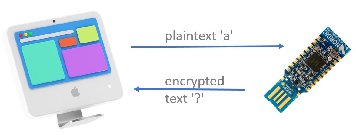
Your task in this section is to decrypt the substitution cipher encrypted ASCII string stored in the Dongle using one of the stack-allocated maps in the heapless crate. The string has been encrypted using simple substitution.
Preparing the Dongle
✅ Flash the puzzle.hex program on the Dongle. Follow the instructions from the "nRF52840 Dongle" section but flash the puzzle.hex program instead of the loopback.hex one -- don't forget to put the Dongle in bootloader mode before invoking nrfdfu.
Note: If you experienced USB issues with
loopback.hexyou use thepuzzle-nousb*.hexvariants.
Like in the previous sections the Dongle will listen for radio packets -- this time over channel 25 -- while also logging messages over a USB/serial interface.
Sending Messages and Receiving the Dongle's Responses
✅ Open the beginner/apps folder in VS Code; then open the src/bin/radio-puzzle.rs file. Run the program.
This will send a zero sized packet let msg = b"" to the dongle.
❗ The Dongle responds to the DK's requests wirelessly (i.e. by sending back radio packets) as well. You'll see the dongle responses printed by the DK. This means you don't have to worry if serial-term doesn't work on your machine.
✅ Try sending one-byte sized packets. ✅ Try sending longer packets.
What happens?
❗ The Dongle responds to the DK's requests wirelessly (i.e. by sending back radio packets) as well. You'll see the dongle responses printed by the DK. This means you don't have to worry if serial-term doesn't work on your machine.
Answer
The Dongle will respond differently depending on the length of the incoming packet:
- On zero-sized packets it will respond with the encrypted string.
- On one-byte sized packets it will respond with the direct mapping from a plaintext letter (single
u8value) -- the letter contained in the packet -- to the ciphertext letter (u8value). - On packets of any other length the Dongle will respond with the string
correctif it received the decrypted string, otherwise it will respond with theincorrectstring.
The Dongle will always respond with packets that are valid UTF-8 so you can use str::from_utf8 on the response packets.
This step is illustrated in src/bin/radio-puzzle-1.rs
From here on, the exercise can be solved in multiple ways. If you have an idea on how to go from here and what tools to use, you can work on your own. If you don't have an idea what to do next or what tools to use, we'll provide a guide on the next page.
Help
Use a dictionary.
Our suggestion is to use a dictionary / map. std::collections::HashMap is not available in no_std code (without linking to a global allocator) but you can use one of the stack-allocated maps in the heapless crate. It supplies a stack-allocated, fixed-capacity version of the std::Vec type which will come in handy to store byte arrays. To store character mappings we recommend using a heapless::LinearMap.
heapless is already declared as a dependency in the Cargo.toml of the project so you can directly import it into the application code using a use statement.
use heapless::Vec;         // like `std::Vec` but stack-allocated
use heapless::LinearMap; // a dictionary / map
use heapless::consts::*;   // defines U16, U32, U64... etc. to set the size of the LinearMap

fn main() {
    // A hash map with a capacity of 16 key-value pairs allocated on the stack
    // note that U16 is a heapless constant, not Rust's u16
    let mut my_map = LinearMap::<_, _, U16>::new();
    my_map.insert(b'A', b'~').unwrap();

    // A vector with a fixed capacity of 8 elements allocated on the stack
    // note that U8 is a heapless constant, not Rust's u8
    let mut my_vec = Vec::<_, U8>::new();
    my_vec.push(b'A').unwrap();
}
If you haven't used a stack-allocated collection before note that you'll need to specify the capacity of the collection as a type parameter using one of the "type-level values" in the heapless::consts module (e.g. U8, U64 etc.). The heapless::LinearMap documentation of the heapless crate has some usage examples, as does the heapless::Vec documentation.
Note the difference between character literals and byte literals!
Something you will likely run into while solving this exercise are character literals ('c') and byte literals (b'c'). The former has type char and represent a single Unicode "scalar value". The latter has type u8 (1-byte integer) and it's mainly a convenience for getting the value of ASCII characters, for instance b'A' is the same as the 65u8 literal.
IMPORTANT you do not need to use the str or char API to solve this problem, other than for printing purposes. Work directly with slices of bytes ([u8]) and bytes (u8); and only convert those to str or char when you are about to print them.
P.S. The plaintext string is not stored in puzzle.hex so running strings on it will not give you the answer.
Make sure not to flood the log buffer
When you log more messages than can be moved from the probe to the target, the log buffer will get overwritten, resulting in data loss. This can easily happen when you repeatedly poll the dongle and log the result. The quickest solution to this is to wait a short while until you send the next packet so that the logs can be processed in the meantime.
use core::time::Duration;

#[entry]
fn main() -> ! {

    let mut timer = board.timer;

    for plainletter in 0..=127 {
        /* ... send letter to dongle ... */
        defmt::println!("got response");
        /* ... store output ... */

        timer.wait(Duration::from_millis(20));
    }
}
Recommended Steps:
Each step is demonstrated in a separate example so if for example you only need a quick reference of how to use the map API you can step / example number 2.
-
Send a one letter packet (e.g.
A) to the radio to get a feel for how the mapping works. Then do a few more letters. Check out exampleradio-puzzle-1 -
Get familiar with the dictionary API. Do some insertions and look ups. What happens if the dictionary gets full? See
radio-puzzle-2 -
Next, get mappings from the radio and insert them into the dictionary. See
radio-puzzle-3 -
You'll probably want a buffer to place the plaintext in. We suggest using
heapless::Vecfor this. Seeradio-puzzle-4(NB It is also possible to decrypt the packet in place) -
Simulate decryption: fetch the encrypted string and "process" each of its bytes. See
radio-puzzle-5 -
Now merge steps 3 and 5: build a dictionary, retrieve the secret string and do the reverse mapping to decrypt the message. See
radio-puzzle-6 -
As a final step, send the decrypted string to the Dongle and check if it was correct or not. See
radio-puzzle-7
For your reference, we have provided a complete solution in the src/bin/radio-puzzle-solution.rs file. That solution is based on the seven steps outlined above. Did you solve the puzzle in a different way?
If you solved the puzzle using a Vec buffer you can try solving it without the buffer as a stretch goal. You may find the slice methods that let you mutate its data useful. A solution that does not use the Vec buffer can be found in the radio-puzzle-solution-2 file.
Next Steps
If you've already completed the main workshop tasks or would like to explore more on your own this section has some suggestions.
Collision avoidance
In this section you'll test the collision avoidance feature of the IEEE 802.15.4 radio used by the Dongle and DK.
If you check the API documentation of the Radio abstraction we have been using you'll notice that we haven't used these methods: energy_detection_scan(), set_cca() and try_send().
The first method scans the currently selected channel (see set_channel()), measures the energy level of ongoing radio communication in this channel and returns the maximum energy observed over a span of time. This method can be used to determine what the idle energy level of a channel is. If there's non-IEEE 802.15.4 traffic on this channel the method will return a high value.
Under the 802.15.4 specification, before sending a data packet devices must first check if there's communication going on in the channel. This process is known as Clear Channel Assessment (CCA). The send method we have been used performs CCA in a loop and sends the packet only when the channel appears to be idle. The try_send method performs CCA once and returns the Err variant if the channel appears to be busy. In this failure scenario the device does not send any packet.
The Radio abstraction supports 2 CCA modes: CarrierSense and EnergyDetection. CarrierSense is the default CCA mode and what we have been using in this workshop. CarrierSense will only look for ongoing 802.15.4 traffic in the channel but ignore other traffic like 2.4 GHz WiFi and Bluetooth. The EnergyDetection method is able to detect ongoing non-802.15.4 traffic.
Here are some things for you to try out:
-
First, read the section 6.20.12.4 of the nRF52840 Product Specification, which covers the nRF52840's implementation of CCA.
-
Disconnect the Dongle. Write a program for the DK that scans and reports the energy levels of all valid 802.15.4 channels. In your location which channels have high energy levels when there's no ongoing 802.15.4 traffic? If you can, use an application like WiFi Analyzer to see which WiFi channels are in use in your location. Compare the output of WiFiAnalyzer to the values you got from
energy_detection_scan. Is there a correspondence? Note that WiFi channels don't match in frequency with 802.15.4 channels; some mapping is required to convert between them -- check this illustration for more details about co-existence of 802.15.4 and WiFi.
-
Choose the channel with the highest idle energy. Now write a program on the DK that sets the CCA mode to
EnergyDetectionand then send a packet over this channel usingtry_send. TheEnergyDetectionCCA mode requires a Energy Detection (ED) "threshold" value. Try different threshold values. What threshold value makes thetry_sendsucceed? -
Repeat the previous experiment but use the channel with the lowest idle energy.
-
Pick the channel with the lowest idle energy. Run the
loopbackapp on the Dongle and set its listening channel to the chosen channel. Modify the DK program to perform asendoperation immediately followed by atry_sendoperation. Thetry_sendoperation will collide with the response of the Dongle (remember: the Dongle responds to all incoming packets). Find a ED threshold that detects this collision and makestry_sendreturn theErrvariant.
Interrupt handling
We haven't covered interrupt handling in the workshop but the cortex-m-rt crate provides attributes to declare exception and interrupt handlers: #[exception] and #[interrupt]. You can find documentation about these attributes and how to safely share data with interrupt handlers using Mutexes in the "Concurrency" chapter of the Embedded Rust book.
Another way to deal with interrupts is to use a framework like Real-Time Interrupt-driven Concurrency (RTIC); this framework has a book that explains how you can build reactive applications using interrupts. We use this framework in the advanced level workshop.
Starting a Project from Scratch
So far we have been using a pre-made Cargo project to work with the nRF52840 DK. In this section we'll see how to create a new embedded project for any microcontroller.
Identify the microcontroller
The first step is to identify the microcontroller you'll be working with. The information about the microcontroller you'll need is:
1. Its processor architecture and sub-architecture.
This information should be in the device's data sheet or manual. In the case of the nRF52840, the processor is an ARM Cortex-M4 core. With this information you'll need to select a compatible compilation target. rustup target list will show all the supported compilation targets.
$ rustup target list
(..)
thumbv6m-none-eabi
thumbv7em-none-eabi
thumbv7em-none-eabihf
thumbv7m-none-eabi
thumbv8m.base-none-eabi
thumbv8m.main-none-eabi
thumbv8m.main-none-eabihf
The compilation targets will usually be named using the following format: $ARCHITECTURE-$VENDOR-$OS-$ABI, where the $VENDOR field is sometimes omitted. Bare metal and no_std targets, like microcontrollers, will often use none for the $OS field. When the $ABI field ends in hf it indicates that the output ELF uses the hardfloat Application Binary Interface (ABI).
The thumb targets listed above are all the currently supported ARM Cortex-M targets. The table below shows the mapping between compilation targets and ARM Cortex-M processors.
| Compilation target | Processor |
|---|---|
thumbv6m-none-eabi | ARM Cortex-M0, ARM Cortex-M0+ |
thumbv7m-none-eabi | ARM Cortex-M3 |
thumbv7em-none-eabi | ARM Cortex-M4, ARM Cortex-M7 |
thumbv7em-none-eabihf | ARM Cortex-M4F, ARM Cortex-M7F |
thumbv8m.base-none-eabi | ARM Cortex-M23 |
thumbv8m.main-none-eabi | ARM Cortex-M33, ARM Cortex-M35P |
thumbv8m.main-none-eabihf | ARM Cortex-M33F, ARM Cortex-M35PF |
The ARM Cortex-M ISA is backwards compatible so for example you could compile a program using the thumbv6m-none-eabi target and run it on an ARM Cortex-M4 microcontroller. This will work but using the thumbv7em-none-eabi results in better performance (ARMv7-M instructions will be emitted by the compiler) so it should be preferred.
2. Its memory layout.
In particular, you need to identify how much Flash and RAM memory the device has and at which address the memory is exposed. You'll find this information in the device's data sheet or reference manual.
In the case of the nRF52840, this information is in section 4.2 (Figure 2) of its Product Specification. It has:
- 1 MB of Flash that spans the address range:
0x0000_0000-0x0010_0000. - 256 KB of RAM that spans the address range:
0x2000_0000-0x2004_0000.
The cortex-m-quickstart project template
With all this information you'll be able to build programs for the target device. The cortex-m-quickstart project template provides the most frictionless way to start a new project for the ARM Cortex-M architecture -- for other architectures check out other project templates by the rust-embedded organization.
The recommended way to use the quickstart template is through the cargo-generate tool:
$ cargo generate --git https://github.com/rust-embedded/cortex-m-quickstart
But it may be difficult to install the cargo-generate tool on Windows due to its libgit2 (C library) dependency. Another option is to download a snapshot of the quickstart template from GitHub and then fill in the placeholders in Cargo.toml of the snapshot.
Once you have instantiated a project using the template you'll need to fill in the device-specific information you collected in the two previous steps:
1. Change the default compilation target in .cargo/config
[build]
target = "thumbv7em-none-eabi"
For the nRF52840 you can choose either thumbv7em-none-eabi or thumbv7em-none-eabihf. If you are going to use the FPU then select the hf variant.
2. Enter the memory layout of the chip in memory.x
MEMORY
{
  /* NOTE 1 K = 1 KiBi = 1024 bytes */
  FLASH : ORIGIN = 0x00000000, LENGTH = 1M
  RAM : ORIGIN = 0x20000000, LENGTH = 256K
}
3. cargo build now will cross compile programs for your target device.
If there's no template or signs of support for a particular architecture under the rust-embedded organization then you can follow the embedonomicon to bootstrap support for the new architecture by yourself.
Flashing the program
To flash the program on the target device you'll need to identify the on-board debugger, if the development board has one. Or choose an external debugger, if the development board exposes a JTAG or SWD interface via some connector.
If the hardware debugger is supported by the probe-rs project -- for example J-Link, ST-Link or CMSIS-DAP -- then you'll be able to use probe-rs-based tools like cargo-flash and cargo-embed. This is the case of the nRF52840 DK: it has an on-board J-Link probe.
If the debugger is not supported by probe-rs then you'll need to use OpenOCD or vendor provided software to flash programs on the board.
If the board does not expose a JTAG, SWD or similar interface then the microcontroller probably comes with a bootloader as part of its stock firmware. In that case you'll need to use dfu-util or a vendor specific tool like nrfdfu or nrfutil to flash programs onto the chip. This is the case of the nRF52840 Dongle.
Getting output
If you are using one of the probes supported by probe-rs then you can use the rtt-target library to get text output on cargo-embed. The logging functionality we used in the examples is implemented using the rtt-target crate.
If that's not the case or there's no debugger on board then you'll need to add a HAL before you can get text output from the board.
Adding a Hardware Abstraction Layer (HAL)
Now you can hopefully run programs and get output from them. To use the hardware features of the device you'll need to add a HAL to your list of dependencies. crates.io, lib.rs and awesome embedded Rust are good places to search for HALs.
After you find a HAL you'll want to get familiar with its API through its API docs and examples. HAL do not always expose the exact same API, specially when it comes to initialization and configuration of peripherals. However, most HAL will implement the embedded-hal traits. These traits allow inter-operation between the HAL and driver crates. These driver crates provide functionality to interface external devices like sensors, actuators and radios over interfaces like I2C and SPI.
If no HAL is available for your device then you'll need to build one yourself. This is usually done by first generating a Peripheral Access Crate (PAC) from a System View Description (SVD) file using the svd2rust tool. The PAC exposes a low level, but type safe, API to modify the registers on the device. Once you have a PAC you can use of the many HALs on crates.io as a reference; most of them are implemented on top of svd2rust-generated PACs.
Hello, 💡
Now that you've set up your own project from scratch, you could start playing around with it by turning on one of the DK's on-board LEDs using only the HAL. Some hints that might be helpful there:
- The Nordic Infocenter tells you which LED is connected to which pin.
Advanced Workbook
In this workshop you'll learn to:
- work with registers and peripherals from Rust
- handle external events in embedded Rust applications
- debug evented applications
- test
no_stdcode
To put these concepts and techniques in practice you'll write a toy USB device application that gets enumerated and configured by the host. This embedded application will run in a fully event driven fashion: only doing work when the host asks for it.
You have received two development boards for this workshop. We'll only use the nRF52840 Development Kit, the larger of the two, in the advanced workshop.
The nRF52840 Development Kit
The board has two USB ports: J2 and J3 and an on-board J-Link programmer / debugger -- there are instructions to identify the ports in a previous section. USB port J2 is the J-Link's USB port. USB port J3 is the nRF52840's USB port. Connect the Development Kit to your computer using both ports.
The nRF52840
Both development boards have an nRF52840 microcontroller. Here are some details about it that are relevant to this workshop.
- single core ARM Cortex-M4 processor clocked at 64 MHz
- 1 MB of Flash (at address
0x0000_0000) - 256 KB of RAM (at address
0x2000_0000) - IEEE 802.15.4 and BLE (Bluetooth Low Energy) compatible radio
- USB controller (device function)
Code Organization
The advanced folder contains both "host" code, code that will run on the host, and "firmware" code, code that will run on the nRF52840 SoC. "host" and "firmware" source code has been placed in different Cargo workspaces so that each can be compiled with different compilation profiles. The host workspace will be natively compiled, whereas the firmware workspace will be cross-compiled for the ARM Cortex-M architecture.
$ cd advanced

$ tree -L 1 .
.
├── common
├── firmware
├── host
└── README.md
In addition to these two workspaces there's a third folder called "common". This folder contains no_std code that can be depended on by either "host" code or "firmware" code.
Listing USB Devices
✅ To list all USB devices, run cargo xtask usb-list from the advanced folder.
$ cargo xtask usb-list
Bus 002 Device 001: ID 1d6b:0003
Bus 001 Device 002: ID 0cf3:e300
Bus 001 Device 003: ID 0c45:6713
Bus 001 Device 001: ID 1d6b:0002
Bus 001 Device 010: ID 1366:1015 <- J-Link on the nRF52840 Development Kit
The goal of this workshop is to get the nRF52840 SoC to show in this list. The embedded application will use the vendor ID (VID) and product ID (PID) defined in advanced/common/consts; cargo xtask usb-list will highlight the USB device that matches that VID PID pair.
$ # expected output
$ cargo xtask usb-list
Bus 002 Device 001: ID 1d6b:0003
Bus 001 Device 002: ID 0cf3:e300
Bus 001 Device 003: ID 0c45:6713
Bus 001 Device 001: ID 1d6b:0002
Bus 001 Device 010: ID 1366:1015 <- J-Link on the nRF52840 Development Kit
Bus 001 Device 059: ID 2020:0717 <- nRF52840 on the nRF52840 Development Kit
Hello, world!
In this section, we'll set up the integration in VS Code and run the first program.
✅ Open the advanced/firmware folder in VS Code and open the src/bin/hello.rs file.
Note: To ensure full rust-analyzer support, do not open the whole
embedded-trainings-2020folder.
Give rust-analyzer some time to analyze the file and its dependency graph. When it's done, a "Run" button will appear over the main function. If it doesn't appear on its own, type something in the file, delete and save. This should trigger a re-load.
✅ Click the "Run" button to run the application on the microcontroller.
If you are not using VS code run the cargo run --bin hello command from the advanced/firmware folder.
NOTE if you run into an error along the lines of "Debug power request failed" retry the operation and the error should disappear
The firmware workspace has been configured to cross-compile applications to the ARM Cortex-M architecture and then run them using the probe-run custom Cargo runner. The probe-run tool will load and run the embedded application on the microcontroller and collect logs from the microcontroller.
The probe-run process will terminate when the microcontroller enters the "halted" state. From the embedded application, one can enter the "halted" state using the asm::bkpt function. For convenience, an exit function is provided in the dk Hardware Abstraction Layer (HAL). This function is divergent like std::process::exit (fn() -> !) and can be used to halt the device and terminate the probe-run process.
Note that when the probe-run tool sees the device enter the halted state it will proceed to reset-halt the device. This is particularly important when writing USB applications because simply leaving the device in a halted state will make it appear as an unresponsive USB device to the host. Some OSes (e.g. Linux) will try to make an unresponsive device respond by power cycling the entire USB bus -- this will cause all other USB devices on the bus to be re-enumerated. Reset-halting the device will cause it to be electrically disconnected from the host USB bus and avoid the "power cycle the whole USB bus" scenario.
Checking the API documentation
We'll be using the dk Hardware Abstraction Layer. It's good to have its API documentation handy. You can generate the documentation for that crate from the command line:
✅ Run the following command from within the advanced/firmware folder. It will open the generated documentation in your default web browser.
$ cargo doc -p dk --open
NOTE: If you are using Safari and the documentation is hard to read due to missing CSS, try opening it in a different browser.
RTIC hello
RTIC, Real-Time Interrupt-driven Concurrency, is a framework for building evented, time sensitive applications.
✅ Open the src/bin/rtic-hello.rs file.
RTIC applications are written in RTIC's Domain Specific Language (DSL). The DSL extends Rust syntax with custom attributes like #[init] and #[idle].
RTIC makes a clearer distinction between the application's initialization phase, the #[init] function, and the application's main loop or main logic, the #[idle] function. The initialization phase runs with interrupts disabled and interrupts are re-enabled before the idle function is executed.
rtic::app is a procedural macro that generates extra Rust code, in addition to the user's functions. The fully expanded version of the macro can be found in the file target/rtic-expansion.rs. This file will contain the expansion of the procedural macro for the last compiled RTIC application.
✅ Build the rtic-hello example and look at the generated rtic-expansion.rs file.
You can use rustfmt on target/rtic-expansion.rs to make the generated code easier to read. Among other things, the file should contain the following lines. Note that interrupts are disabled during the execution of the init function:
unsafe extern "C" fn main() -> ! {
    rtic::export::interrupt::disable();
    let mut core: rtic::export::Peripherals = rtic::export::Peripherals::steal().into();
    #[inline(never)]
    fn __rtic_init_resources<F>(f: F)
    where
        F: FnOnce(),
    {
        f();
    }
    __rtic_init_resources(|| {
        let (shared_resources, local_resources, mut monotonics) =
            init(init::Context::new(core.into()));
        rtic::export::interrupt::enable();
            });
    idle(idle::Context::new(&rtic::export::Priority::new(0)))
}
Dealing with Registers
In this and the next section we'll look into RTIC's event handling features. To explore these features we'll use the action of connecting a USB cable to the DK's port J2 as the event we'd like to handle.
✅ Open the src/bin/events.rs file.
We'll read the code and explain, what it does.
The example application enables the signaling of this "USB power" event in the init function. This is done using the low level register API generated by the svd2rust tool. The register API was generated from a SVD (System View Description) file, a file that describes all the peripherals and registers, and their memory layout, on a device. In our case the device was the nRF52840; a sample SVD file for this microcontroller can be found here.
In the svd2rust API, peripherals are represented as structs. The fields of each peripheral struct are the registers associated to that peripheral. Each register field exposes methods to read and write to the register in a single memory operation.
The read and write methods take closure arguments. These closures in turn grant access to a "constructor" value, usually named r or w, which provides methods to modify the bitfields of a register. At the same time the API of these "constructors" prevent you from modifying the reserved parts of the register: you cannot write arbitrary values into registers; you can only write valid values into registers.
Apart from the read and write methods there's a modify method that performs a read-modify-write operation on the register; this API is also closure-based. The svd2rust-generated API is documented in detail in the svd2rust crate starting at the Peripheral API section.
In Cortex-M devices interrupt handling needs to be enabled on two sides: on the peripheral side and on the core side. The register operations done in init take care of the peripheral side. The core side of the operation involves writing to the registers of the Nested Vector Interrupt Controller (NVIC) peripheral. This second part doesn't need to be done by the user in RTIC applications because the framework takes care of it.
Event Handling
Below the idle function you'll see a #[task] handler, a function. This task is bound to the POWER_CLOCK interrupt signal and will be executed, function-call style, every time the interrupt signal is raised by the hardware.
✅ Run the events application. Then connect a micro-USB cable to your PC/laptop then connect the other end to the DK (port J3). You'll see the "POWER event occurred" message after the cable is connected.
Note that all tasks will be prioritized over the idle function so the execution of idle will be interrupted (paused) by the on_power_event task. When the on_power_event task finishes (returns) the execution of the idle will be resumed. This will become more obvious in the next section.
Try this: add an infinite loop to the end of init so that it never returns. Now run the program and connect the USB cable. What behavior do you observe? How would you explain this behavior? (hint: look at the rtic-expansion.rs file: under what conditions is the init function executed?)
Task State
Now let's say we want to change the previous program to count how many times the USB cable (port J3) has been connected and disconnected.
✅ Open the src/bin/resource.rs file.
Tasks run from start to finish, like functions, in response to events. To preserve some state between the different executions of a task we can add a resource to the task. In RTIC, resources are the mechanism used to share data between different tasks in a memory safe manner but they can also be used to hold task state.
To get the desired behavior we'll want to store some counter in the state of the on_power_event task.
The starter code shows the syntax to declare a resource, the Resources struct, and the syntax to associate a resource to a task, the resources list in the #[task] attribute.
In the starter code a resource is used to move (by value) the POWER peripheral from init to the on_power_event task. The POWER peripheral then becomes part of the state of the on_power_event task and can be persistently accessed throughout calls to on_power_event() through a reference. The resources of a task are available via the Context argument of the task.
To elaborate more on this move action: in the svd2rust API, peripheral types like POWER are singletons (only a single instance of the type can ever exist). The consequence of this design is that holding a peripheral instance, like POWER, by value means that the function (or task) has exclusive access, or ownership, over the peripheral. This is the case of the init function: it owns the POWER peripheral but then transfers ownership over it to a task using the resource initialization mechanism.
We have moved the POWER peripheral into the task because we want to clear the USBDETECTED interrupt flag after it has been set by the hardware. If we miss this step the on_power_event task (function) will be called again once it returns and then again and again and again (ad infinitum).
Also note that in the starter code the idle function has been modified. Pay attention to the logs when you run the starter code.
✅ Modify the program so that it prints the number of times the USB cable has been connected to the DK every time the cable is connected, as shown below.
USBDETECTED interrupt enabled
idle: going to sleep
on_power_event: cable connected 1 time
idle: woke up
idle: going to sleep
on_power_event: cable connected 2 times
idle: woke up
idle: going to sleep
on_power_event: cable connected 3 times
You can find a solution to this exercise in the resource-solution.rs file.
USB Enumeration
Check this miro board for an overview.
A USB device, like the nRF52840, can be one of these three states: the Default state, the Address state or the Configured state. After being powered the device will start in the Default state. The enumeration process will take the device from the Default state to the Address state. As a result of the enumeration process the device will be assigned an address, in the range 1..=127, by the host.
The USB protocol is complex so we'll leave out many details and focus only on the concepts required to get enumeration and configuration working. There are also several USB specific terms so we recommend checking chapter 2, "Terms and Abbreviations", of the USB specification (linked at the bottom of this document) every now and then.
Each OS may perform the enumeration process slightly differently but the process will always involve these host actions:
- USB reset. This will put the device in the Default state, regardless of what state it was in.
- GET_DESCRIPTOR request to get the device descriptor.
- SET_ADDRESS request to assign an address to the device.
These host actions will be perceived as events by the nRF52840. During this workshop, we will gradually parse and handle these events and learn more about Embedded Rust along the way.
There are more USB concepts involved that we'll need to cover, like descriptors, configurations, interfaces and endpoints but for now let's see how to handle USB events.
For each step of the course, we've prepared a usb-<n>.rs file that gives you a base structure and hints on how to proceed. The matching usb-<n>-solution.rs contains a sample solution should you need it. Switch from usb-<n>.rs to usb-<n+1>.rs when instructed and continue working from there. Please keep the USB cable plugged into J3 through all these exercises.
USB-1: Dealing with USB Events
The USBD peripheral on the nRF52840 contains a series of registers, called EVENTS registers, that indicate the reason for entering the USBD event handler. These events must be handled by the application to complete the enumeration process.
✅ Open the firmware/src/bin/usb-1.rs file.
In this starter code the USBD peripheral is initialized in init and a task, named main, is bound to the interrupt signal USBD. This task will be called every time a new USBD event needs to be handled. The main task uses usbd::next_event() to check all the event registers; if any event is set (occurred) then the function returns the event, represented by the Event enum, wrapped in the Some variant. This Event is then passed to the on_event function for further processing.
✅ Connect the USB cable to the port J3 then run the starter code.
❗️ Keep the cable connected to the J3 port for the rest of the workshop
This code will panic because USBRESET is not implemented yet.
✅ Go to fn on_event, line 39. In this section you'll need to implement the following USB events USBRESET and EP0SETUP so that your log output will look like this:
USBD initialized
USB: UsbReset
returning to the Default state
USB: UsbEp0Setup
goal reached; move to the next section
Help
-
USBRESET. This event indicates that the host issued a USB reset signal. According to the USB specification this will move the device from any state to theDefaultstate. Since we are currently not dealing with any other state, you can handle this state by adding a log statement to provide information that this event occurred. -
EP0DATADONE. The USBD peripheral is signaling the end of the DATA stage of a control transfer. Since you won't encounter this event just yet, you can leave it as it is. -
EP0SETUP. The USBD peripheral has detected the SETUP stage of a control transfer. Add a log statement containing "goal reached; move to the next section" and exit the application.
You can find the solution in the usb-1-solution.rs file.
USB Endpoints

Under the USB protocol data transfers occur over endpoints.
Endpoints are similar to UDP or TCP ports in that they allow logical multiplexing of data over a single physical USB bus. USB endpoints, however, have directions: an endpoint can either be an IN endpoint or an OUT endpoint. The direction is always from the perspective of the host so at an IN endpoint data travels from the device to the host and at an OUT endpoint data travels from the host to the device.
Endpoints are identified by their address, a zero-based index, and direction. There are four types of endpoints: control endpoints, bulk endpoints, interrupt endpoints and isochronous endpoints. Each endpoint type has different properties: reliability, latency, etc. In this workshop we'll only need to deal with control endpoints.

All USB devices must use "endpoint 0" as the default control endpoint. "Endpoint 0" actually refers to two endpoints: endpoint 0 IN and endpoint 0 OUT. This endpoint pair is used to establish a control pipe, a bidirectional communication channel between the host and device where data is exchanged using a predefined format. The default control pipe over endpoint 0 is mandatory: it must always be present and must always be active.
For detailed information about endpoints check section 5.3.1, Device Endpoints, of the USB 2.0 specification.
Control Transfers
Before we continue we need to discuss how data transfers work under the USB protocol.
The control pipe handles control transfers, a special kind of data transfer used by the host to issue requests. A control transfer is a data transfer that occurs in three stages: a SETUP stage, an optional DATA stage and a STATUS stage.
During the SETUP stage the host sends 8 bytes of data that identify the control request. Depending on the issued request there may be a DATA stage or not; during the DATA stage data is transferred either from the device to the host or the other way around. During the STATUS stage the device acknowledges, or not, the whole control request.
For detailed information about control transfers check section 5.5, Control Transfers, of the USB 2.0 specification.
USB-2: SETUP Stage
At the end of program usb-1 we received a EP0SETUP event. This event signals the end of the SETUP stage of a control transfer. The nRF52840 USBD peripheral will automatically receive the SETUP data and store it in the registers BMREQUESTTYPE, BREQUEST, WVALUE{L,H}, WINDEX{L,H} and WLENGTH{L,H}.
In usb-2.rs, you will find a short description of each register above the variable into which it should be read.
For in-depth register documentation, refer to sections 6.35.13.31 to 6.35.13.38 of the nRF52840 Product Specification.
Writing a parser for the data of this SETUP stage.
❗️ Keep the cable connected to the J3 port for the rest of the workshop
✅ Parse GET_DESCRIPTOR requests for DEVICE descriptors.
Modify Request::parse() in advanced/common/usb/src/lib.rs to recognize a GET_DESCRIPTOR request of type DEVICE so that the get_descriptor_device test passes. Note that the parser already handles SET_ADDRESS requests.
Getting Started:
1. Writing code that can be tested
When you need to write some no_std code that does not involve device-specific I/O you should consider writing it as a separate crate. This way, you can test it on your development machine (e.g. x86_64) using the standard cargo test functionality.
So that's what we'll do here. In advanced/common/usb/lib.rs you'll find starter code for writing a no_std SETUP data parser. The starter code contains some unit tests; you can run them with cargo test (from within the usb folder) or you can use Rust Analyzer's "Test" button in VS code.
The definition of Descriptor::Configuration as well as the associated test has been "commented out" using an #[cfg(TODO)] attribute because it is not handled by the firmware yet. Delete the #[cfg(TODO)] so that the unit tests can access it. This pattern is used for enum members and test functions throughout this workshop, so keep it in mind should you see it again.
2. Description of GET_DESCRIPTOR request
We can recognize a GET_DESCRIPTOR request by the following properties:
bmRequestTypeis 0b10000000bRequestis 6 (i.e. the GET_DESCRIPTOR Request Code, defined in table 9-4 in the USB spec)
3. Description of DEVICE descriptor requests In this task, we only want to parse DEVICE descriptor requests. They have the following properties:
- the descriptor type is 1 (i.e. DEVICE, defined in table 9-5 of the USB spec)
- the descriptor index is 0
- the wIndex is 0 for our purposes
- ❗️you need to fetch the descriptor type from the high byte of
wValue, and the descriptor index from the the low byte ofwValue
Check section 9.4.3 of the USB specification for a very detailed description of the requests. All the constants we'll be using are also described in Tables 9-3, 9-4 and 9-5 of the same document.
4. Remember that you can define binary literals by prefixing them with 0b.
5. You can use bit shifts (>>) and casts (as u8) to get the high/low bytes of wValue.
6. Return Err if properties aren't met.
You will also find this information in the // TODO implement ... comment in the Request::parse() function of lib.rs file.
NOTE: If you'd like to learn more, take a look at Section 9.4.3 Get Descriptor of the USB specification.
See advanced/common/usb/solution-get-descriptor-device.rs for a solution.
✅ Read incoming request information and pass it to the parser:
modify usb-2.rs to read USBD registers and parse the SETUP data when an EP0SETUP event is received.
Getting Started:
-
for a mapping of register names to the
USBDAPI, check the entry fornrf52840_hal::target::usbdin the documentation you've created usingcargo doc -
let bmrequesttype = usbd.bmrequesttype.read().bits() as u8;
-
remember that we've learned how to read registers in
events.rs. -
you will need to put together the higher and lower bits of
wlength,windexandwvalueto get the whole field -
Note: If you're using a Mac, you need to catch
SetAddressrequests returned by the parser as these are sent before the first GetDescriptor request. You can handle them by doing nothing.
Expected Result:
When you have successfully received a GET_DESCRIPTOR request for a Device descriptor you are done. You should see an output like this:
USB: UsbReset @ Duration { secs: 0, nanos: 361145018 }
USB: UsbEp0Setup @ Duration { secs: 0, nanos: 402465820 }
SETUP: bmrequesttype: 0, brequest: 5, wlength: 0, windex: 0, wvalue: 10
USB: UsbEp0Setup @ Duration { secs: 0, nanos: 404754637 }
SETUP: bmrequesttype: 128, brequest: 6, wlength: 8, windex: 0, wvalue: 256
GET_DESCRIPTOR Device [length=8]
Goal reached; move to the next section
`dk::exit()` called; exiting ...
Note:
wlength/lengthcan vary depending on the OS, USB port (USB 2.0 vs USB 3.0) or the presence of a USB hub so you may see a different value.
You can find a solution to this step in advanced/firmware/src/bin/usb-2-solution.rs.
Device Descriptor

After receiving a GET_DESCRIPTOR request during the SETUP stage the device needs to respond with a descriptor during the DATA stage.
A descriptor is a binary encoded data structure sent by the device to the host. The device descriptor, in particular, contains information about the device, like its product and vendor identifiers and how many configurations it has. The format of the device descriptor is specified in section 9.6.1, Device, of the USB specification.
As far as the enumeration process goes, the most relevant fields of the device descriptor are the number of configurations and bcdUSB, the version of the USB specification the devices adheres to. In bcdUSB you should report compatibility with USB 2.0.
What about (the number of) configurations?
A configuration is akin to an operation mode. USB devices usually have a single configuration that will be the only mode in which they'll operate, for example a USB mouse will always act as a USB mouse. Some devices, though, may provide a second configuration for the purpose of firmware upgrades. For example a printer may enter DFU (Device Firmware Upgrade) mode, a second configuration, so that a user can update its firmware; while in DFU mode the printer will not provide printing functionality.
The specification mandates that a device must have at least one available configuration so we can report a single configuration in the device descriptor.
USB-3: DATA Stage
The next step is to respond to the GET_DESCRIPTOR request with a device descriptor.
❗️ Keep the cable connected to the J3 port for the rest of the workshop
✅ Open the file src/bin/usb-3.rs.
Part of this response is already implemented. We'll go through this.
We'll use the dk::usb::Ep0In abstraction. An instance of it is available in the board value (#[init] function). The first step is to make this Ep0In instance available to the on_event function.
The Ep0In API has two methods: start and end. start is used to start a DATA stage; this method takes a slice of bytes ([u8]) as argument; this argument is the response data. The end method needs to be called after start, when the EP0DATADONE event is raised, to complete the control transfer. Ep0In will automatically issue the STATUS stage that must follow the DATA stage.
✅ Handle the EP0DATADONE event by calling the end method of the EP0In API.
✅ Implement the response to the GET_DESCRIPTOR request. Extend usb-3.rs so that it uses Ep0In to respond to the GET_DESCRIPTOR Device request (and only to that request).
Values of the device descriptor
bLength = 18, the size of the descriptor (must always be this value)bDescriptorType = 1, device descriptor type (must always be this value)bDeviceClass = bDeviceSubClass = bDeviceProtocol = 0, these are unimportant for enumerationbMaxPacketSize0 = 64, this is the most performant option (minimizes exchanges between the device and the host) and it's assumed by theEp0InabstractionidVendor = consts::VID, value expected bycargo xtask usb-list(*)idProduct = consts::PID, value expected bycargo xtask usb-list(*)bcdDevice = 0x0100, this means version 1.0 but any value should doiManufacturer = iProduct = iSerialNumber = None, string descriptors not supportedbNumConfigurations = 1, must be at least1so this is the minimum value
(*) the
commoncrate refers to the crate in theadvanced/commonfolder. It is already part of thefirmwarecrate dependencies.
Use the usb2::device::Descriptor abstraction
Although you can create the device descriptor by hand as an array filled with magic values we strongly recommend you use the usb2::device::Descriptor abstraction. The crate is already in the dependency list of the project; you can open its API documentation with the following command: cargo doc -p usb2 --open.
The length of the device descriptor
The usb2::device::Descriptor struct does not have bLength and bDescriptorType fields. Those fields have fixed values according to the USB spec so you cannot modify or set them. When bytes() is called on the Descriptor value the returned array, the binary representation of the descriptor, will contain those fields set to their correct value.
The device descriptor is 18 bytes long but the host may ask for fewer bytes (see wlength field in the SETUP data). In that case you must respond with the amount of bytes the host asked for. The opposite may also happen: wlength may be larger than the size of the device descriptor; in this case your answer must be 18 bytes long (do not pad the response with zeroes).
Expected log output
Once you have successfully responded to the GET_DESCRIPTOR Device request you should get logs like these (if you are logging like usb-3 does):
USB: UsbReset @ Duration { secs: 0, nanos: 211334227 }
USB: UsbEp0Setup @ Duration { secs: 0, nanos: 252380370 }
SETUP: bmrequesttype: 0, brequest: 5, wlength: 0, windex: 0, wvalue: 52
USB: UsbEp0Setup @ Duration { secs: 0, nanos: 254577635 }
SETUP: bmrequesttype: 128, brequest: 6, wlength: 8, windex: 0, wvalue: 256
GET_DESCRIPTOR Device [length=8]
EP0IN: start 8B transfer
USB: UsbEp0DataDone @ Duration { secs: 0, nanos: 254852293 }
EP0IN: transfer done
USB: UsbEp0Setup @ Duration { secs: 0, nanos: 257568358 }
SETUP: bmrequesttype: 128, brequest: 6, wlength: 18, windex: 0, wvalue: 256
GET_DESCRIPTOR Device [length=18]
EP0IN: start 18B transfer
USB: UsbEp0DataDone @ Duration { secs: 0, nanos: 257843016 }
EP0IN: transfer done
USB: UsbEp0Setup @ Duration { secs: 0, nanos: 259674071 }
SETUP: bmrequesttype: 128, brequest: 6, wlength: 9, windex: 0, wvalue: 512
ERROR unknown request (goal achieved if GET_DESCRIPTOR Device was handled before)
`dk::exit()` called; exiting ...
A solution to this exercise can be found in src/bin/usb-3-solution.rs.
Direct Memory Access
🔎 this section covers the implementation of the Ep0In abstraction; it's not necessary to fully understand this section to continue working on the workshop.
Let's zoom into the Ep0In abstraction we used in usb-3.rs.
✅ Open the file. Use VSCode's "Go to Definition" to see the implementation of the Ep0In.start() method.
This is how data transfers over USB work on the nRF52840: for each endpoint there's a buffer in the USBD peripheral. Data sent by the host over USB to a particular endpoint will be stored in the corresponding endpoint buffer. Likewise, data stored in one of these endpoint buffers can be send to the host over USB from that particular endpoint. These buffers are not directly accessible by the CPU but data stored in RAM can be copied into these buffers; likewise, the contents of an endpoint buffer can be copied into RAM. A second peripheral, the Direct Memory Access (DMA) peripheral, can copy data between these endpoint buffers and RAM. The process of copying data in either direction is referred to as "a DMA transfer".
What the start method does is start a DMA transfer to copy bytes into endpoint buffer IN 0; this makes the USBD peripheral send data to the host from endpoint IN 0 fs. The data (bytes), which may be located in Flash or RAM, is first copied into an internal buffer, allocated in RAM, and then the DMA is configured to move the data from this internal buffer to endpoint buffer 0 IN, which is part of the USBD peripheral.
The signature of the start() method does not ensure that:
byteswon't be deallocated before the DMA transfer is over (e.g.bytescould be pointing into the stack), or thatbyteswon't be modified right after the DMA transfer starts (this would be a data race in the general case).
For these two safety reasons the API is implemented using an internal buffer called buffer. The internal buffer has a 'static lifetime so it's guaranteed to never be deallocated -- this prevents issue (a). The busy flag prevents any further modification to the internal buffer -- from the public API -- while the DMA transfer is in progress.
Apart from thinking about lifetimes and explicit data races in the surface API one must internally use memory fences to prevent reordering of memory operations (e.g. by the compiler), which can also cause data races. DMA transfers run in parallel to the instructions performed by the processor and are "invisible" to the compiler.
In the implementation of the start method, data is copied from bytes to the internal buffer (a memcpy() operation) and then the DMA transfer is started with a write to the TASKS_STARTEPIN0 register. The compiler sees the start of the DMA transfer (register write) as an unrelated memory operation so it may move the memcpy() to after the DMA transfer has started. This reordering results in a data race: the processor modifies the internal buffer while the DMA is reading data out from it.
To avoid this reordering a memory fence, dma_start(), is used. The fence pairs with the store operation (register write) that starts the DMA transfer and prevents the previous memcpy(), and any other memory operation, from being move to after the store operation.
Another memory fence, dma_end(), is needed at the end of the DMA transfer. In the general case, this prevents instruction reordering that would result in the processor accessing the internal buffer before the DMA transfer has finished. This is particularly problematic with DMA transfers that modify a region of memory which the processor intends to read after the transfer.
Note: Not relevant to the DMA operation but relevant to the USB specification, the
start()method sets a shortcut in the USBD peripheral to issue a STATUS stage right after the DATA stage is finished. Thanks to this it is not necessary to manually start a STATUS stage after calling theendmethod.
USB-4: Supporting more Standard Requests
After responding to the GET_DESCRIPTOR Device request the host will start sending different requests.
✅ Update the parser in common/usb so that it can handle the following requests:
GET_DESCRIPTOR Configuration, see the section on Handling GET_DESCRIPTOR Configuration RequestsSET_CONFIGURATION, see the section on SET_CONFIGURATION of this course material
The starter common/usb code contains unit tests for these other requests as well as extra Request variants for these requests. All of them have been commented out using a #[cfg(TODO)] attribute which you can remove once you need any new variant or new unit test.
✅ For each green test, extend usb-4.rs to handle the new requests your parser is now able to recognize. Make sure to read the next sections as you're working, since they contain explanations about the concepts used and needed to complete this task.
❗️ Keep the cable connected to the J3 port for the rest of the workshop
If you need a reference, you can find solutions to parsing GET_DESCRIPTOR Configuration and SET_CONFIGURATION requests in the following files:
advanced/common/usb/solution-get-descriptor-configuration.rsadvanced/common/usb/solution-set-configuration.rs
Each file contains just enough code to parse the request in its name and the GET_DESCRIPTOR Device and SET_ADDRESS requests. So you can refer to solution-get-descriptor-configuration.rs without getting "spoiled" about how to parse the SET_CONFIGURATION request.
Error handling in embedded Rust
Since the logic of the EP0SETUP event handling is getting more complex with each added event, you can see that usb-4.rs was refactored to add error handling: the event handling now happens in a separate function that returns a Result. When it encounters an invalid host request, it returns the Err variant which can be handled by stalling the endpoint:
#![allow(unused)]
fn main() {
fn on_event(/* parameters */) {
    match event {
        /* ... */
        Event::UsbEp0Setup => {
            if ep0setup(/* arguments */).is_err() {
                // unsupported or invalid request:
                // TODO add code to stall the endpoint
                defmt::warn!("EP0IN: unexpected request; stalling the endpoint");
            }
        }
    }
}

fn ep0setup(/* parameters */) -> Result<(), ()> {
    let req = Request::parse(/* arguments_*/)?;
    //                                       ^ early returns an `Err` if it occurs

    // TODO respond to the `req`; return `Err` if the request was invalid in this state

    Ok(())
}
}
Note that there's a difference between the error handling done here and the error handling commonly done in std programs. std programs usually bubble up errors to the top main function (using the ? operator), report the error (or chain of errors) and then exit the application with a non-zero exit code. This approach is usually not appropriate for embedded programs as
(1) main cannot return,
(2) there may not be a console to print the error to and/or
(3) stopping the program, and e.g. requiring the user to reset it to make it work again, may not be desirable behavior.
For these reasons in embedded software errors tend to be handled as early as possible rather than propagated all the way up.
This does not preclude error reporting. The above snippet includes error reporting in the form of a defmt::warn! statement. This log statement may not be included in the final release of the program as it may not be useful, or even visible, to an end user but it is useful during development.
Updating Device State
At some point during the initialization you'll receive a SET_ADDRESS request that will move the device from the Default state to the Address state. If you are working on Linux, you'll also receive a SET_CONFIGURATION request that will move the device from the Address state to the Configured state. Additionally, some requests are only valid in certain states– for example SET_CONFIGURATION is only valid if the device is in the Address state. For this reason usb-4.rs will need to keep track of the device's current state.
The device state should be tracked using a resource so that it's preserved across multiple executions of the USBD event handler. The usb2 crate has a State enum with the 3 possible USB states: Default, Address and Configured. You can use that enum or roll your own.
✅ Start tracking and updating the device state to move your request handling forward:
-
Update the handling of the
USBRESETevent: Instead of ignoring it, we now want it to change the state of the USB device. See section 9.1 USB Device States of the USB specification for details on what to do. -
Update the handling of
SET_ADDRESSrequests: See the section on Handling SET_ADDRESS Requests of this tutorial for details. -
Implement the handling of
GET_DESCRIPTOR Configurationrequests: See the section on Handling GET_DESCRIPTOR Configuration Requests of this tutorial for details.
Dealing with unknown requests: Stalling the endpoint
You may come across host requests other than the ones listed in previous sections.
For this situation, the USB specification defines a device-side procedure for "stalling an endpoint", which amounts to the device telling the host that it doesn't support some request.
This procedure should be used to deal with invalid requests, requests whose SETUP stage doesn't match any USB 2.0 standard request, and requests not supported by the device– for instance the SET_DESCRIPTOR request is not mandatory.
✅ Use the dk::usbd::ep0stall() helper function to stall endpoint 0 in usb-4.rs.
Handling SET_ADDRESS Requests
This request should come right after the
GET_DESCRIPTOR Devicerequest if you're using Linux, or be the first request sent to the device by Mac OS.
A SET_ADDRESS request has the following fields as defined by Section 9.4.6 Set Address of the USB spec:
bmrequesttypeis 0b00000000brequestis 5 (i.e. the SET_ADDRESS Request Code, see table 9-4 in the USB spec)wValuecontains the address to be used for all subsequent accesseswIndexandwLengthare 0, there is nowData
It should be handled as follows:
-
If the device is in the
Defaultstate, then- if the requested address stored in
wValuewas0(Nonein theusbAPI) then the device should stay in theDefaultstate - otherwise the device should move to the
Addressstate
- if the requested address stored in
-
If the device is in the
Addressstate, then- if the requested address stored in
wValuewas0(Nonein theusbAPI) then the device should return to theDefaultstate - otherwise the device should remain in the
Addressstate but start using the new address
- if the requested address stored in
-
If the device is in the
Configuredstate this request results in "unspecified" behavior according to the USB specification. You should stall the endpoint in this case.
Note: According to the USB specification the device needs to respond to this request with a STATUS stage -- the DATA stage is omitted. The nRF52840 USBD peripheral will automatically issue the STATUS stage and switch to listening to the requested address (see the USBADDR register) so no interaction with the USBD peripheral is required for this request.
For more details, read the introduction of section 6.35.9 of the nRF52840 Product Specification 1.0.
Handling GET_DESCRIPTOR Configuration Requests
When the host issues a GET_DESCRIPTOR Configuration request the device needs to respond with the requested configuration descriptor plus all the interface and endpoint descriptors associated to that configuration descriptor during the DATA stage.
As a reminder, all GET_DESCRIPTOR request types are share the following properties:
bmRequestTypeis 0b10000000bRequestis 6 (i.e. the GET_DESCRIPTOR Request Code, defined in table 9-4 of the USB specification)
A GET_DESCRIPTOR Configuration request is determined the high byte of its wValue field:
- The high byte of
wValueis 2 (i.e. theCONFIGURATIONdescriptor type, defined in table 9-5 of the USB specification)
In the next sections, let's look into all the concepts required to respond to this request.
Configuration descriptor

The configuration descriptor describes one of the device configurations to the host. The descriptor contains the following information about a particular configuration:
- the total length of the configuration: this is the number of bytes required to transfer this configuration descriptor and the interface and endpoint descriptors associated to it
- its number of interfaces -- must be >= 1
- its configuration value -- this is not an index and can be any non-zero value
- whether the configuration is self-powered
- whether the configuration supports remote wakeup
- its maximum power consumption
The full format of the configuration descriptor is specified in section 9.6.3, Configuration, of the USB specification.
Interface
We have covered configurations and endpoints but what is an interface?

An interface is closest to a USB device's function. For example, a USB mouse may expose a single HID (Human Interface Device) interface to report user input to the host. USB devices can expose multiple interfaces within a configuration. For example, the nRF52840 Dongle could expose both a CDC ACM interface (AKA virtual serial port) and a HID interface; the first interface could be used for (defmt::println!-style) logs; and the second one could provide a RPC (Remote Procedure Call) interface to the host for controlling the nRF52840's radio.
An interface is made up of one or more endpoints. To give an example, a HID interface can use two (interrupt) endpoints, one IN and one OUT, for bidirectional communication with the host. A single endpoint cannot be used by more than one interface with the exception of the special "endpoint 0", which can be (and usually is) shared by all interfaces.
For detailed information about interfaces check section 9.6.5, Interface, of the USB specification.
Interface descriptor
The interface descriptor describes one of the device interfaces to the host. The descriptor contains the following information about a particular interface:
- its interface number -- this is a zero-based index
- its alternate setting -- this allows configuring the interface
- its number of endpoints
- class, subclass and protocol -- these define the interface (HID, or TTY ACM, or DFU, etc.) according to the USB specification
The number of endpoints can be zero and endpoint zero must not be accounted when counting endpoints.
The full format of the interface descriptor is specified in section 9.6.5, Interface, of the USB specification.
Endpoint descriptor

We will not need to deal with endpoint descriptors in this workshop but they are specified in section 9.6.6, Endpoint, of the USB specification.
Response
So how should we respond to the host? As our only goal is to be enumerated we'll respond with the minimum amount of information possible.
✅ First, check the request: Configuration descriptors are requested by index, not by their configuration value. Since we reported a single configuration in our device descriptor the index in the request must be zero. Any other value should be rejected by stalling the endpoint (see section Dealing with unknown requests: Stalling the endpoint for more information).
✅ Next, create and send a response: The response should consist of the configuration descriptor, followed by interface descriptors and then by (optional) endpoint descriptors. We'll include a minimal single interface descriptor in the response. Since endpoints are optional we will include none.
The configuration descriptor and one interface descriptor will be concatenated in a single packet so this response should be completed in a single DATA stage.
The configuration descriptor in the response should contain these fields:
bLength = 9, the size of this descriptor (must always be this value)bDescriptorType = 2, configuration descriptor type (must always be this value)wTotalLength = 18= one configuration descriptor (9 bytes) and one interface descriptor (9 bytes)bNumInterfaces = 1, a single interface (the minimum value)bConfigurationValue = 42, any non-zero value will doiConfiguration = 0, string descriptors are not supportedbmAttributes { self_powered: true, remote_wakeup: false }, self-powered due to the debugger connectionbMaxPower = 250(500 mA), this is the maximum allowed value but any (non-zero?) value should do
The interface descriptor in the response should contain these fields:
bLength = 9, the size of this descriptor (must always be this value)bDescriptorType = 4, interface descriptor type (must always be this value)bInterfaceNumber = 0, this is the first, and only, interfacebAlternateSetting = 0, alternate settings are not supportedbNumEndpoints = 0, no endpoint associated to this interface (other than the control endpoint)bInterfaceClass = bInterfaceSubClass = bInterfaceProtocol = 0, does not adhere to any specified USB interfaceiInterface = 0, string descriptors are not supported
Again, we strongly recommend that you use the usb2::configuration::Descriptor and usb2::interface::Descriptor abstractions here. Each descriptor instance can be transformed into its byte representation using the bytes method -- the method returns an array. To concatenate both arrays you can use an stack-allocated heapless::Vec buffer. If you haven't the heapless crate before you can find example usage in the the src/bin/vec.rs file.
NOTE: the
usb2::configuration::Descriptorandusb2::interface::Descriptorstructs do not havebLengthandbDescriptorTypefields. Those fields have fixed values according to the USB spec so you cannot modify or set them. Whenbytes()is called on theDescriptorvalue the returned array, the binary representation of the descriptor, will contain those fields set to their correct value.
SET_CONFIGURATION (Linux & Mac OS)
On Linux and Mac OS, the host will likely send a SET_CONFIGURATION request right after enumeration to put the device in the Configured state. For now you can stall the request. It is not necessary at this stage because the device has already been enumerated.
Idle State
Once you have handled all the previously covered requests the device should be enumerated and remain idle awaiting for a new host request. Your logs may look like this:
INFO:usb_4 -- USB: UsbReset @ 318.66455ms
INFO:usb_4 -- USB reset condition detected
INFO:usb_4 -- USB: UsbEp0Setup @ 391.418456ms
INFO:usb_4 -- EP0: GetDescriptor { descriptor: Device, length: 64 }
INFO:dk::usbd -- EP0IN: start 18B transfer
INFO:usb_4 -- USB: UsbEp0DataDone @ 391.723632ms
INFO:usb_4 -- EP0IN: transfer complete
INFO:dk::usbd -- EP0IN: transfer done
INFO:usb_4 -- USB: UsbReset @ 442.016601ms
INFO:usb_4 -- USB reset condition detected
INFO:usb_4 -- USB: UsbEp0Setup @ 514.709471ms
INFO:usb_4 -- EP0: SetAddress { address: Some(17) }
INFO:usb_4 -- USB: UsbEp0Setup @ 531.37207ms
INFO:usb_4 -- EP0: GetDescriptor { descriptor: Device, length: 18 }
INFO:dk::usbd -- EP0IN: start 18B transfer
INFO:usb_4 -- USB: UsbEp0DataDone @ 531.646727ms
INFO:usb_4 -- EP0IN: transfer complete
INFO:dk::usbd -- EP0IN: transfer done
INFO:usb_4 -- USB: UsbEp0Setup @ 531.829832ms
INFO:usb_4 -- EP0: GetDescriptor { descriptor: DeviceQualifier, length: 10 }
ERROR:usb_4 -- EP0IN: unexpected request; stalling the endpoint
INFO:usb_4 -- USB: UsbEp0Setup @ 532.226562ms
INFO:usb_4 -- EP0: GetDescriptor { descriptor: DeviceQualifier, length: 10 }
ERROR:usb_4 -- EP0IN: unexpected request; stalling the endpoint
INFO:usb_4 -- USB: UsbEp0Setup @ 532.592772ms
INFO:usb_4 -- EP0: GetDescriptor { descriptor: DeviceQualifier, length: 10 }
ERROR:usb_4 -- EP0IN: unexpected request; stalling the endpoint
INFO:usb_4 -- USB: UsbEp0Setup @ 533.020018ms
INFO:usb_4 -- EP0: GetDescriptor { descriptor: Configuration { index: 0 }, length: 9 }
INFO:dk::usbd -- EP0IN: start 9B transfer
INFO:usb_4 -- USB: UsbEp0DataDone @ 533.386228ms
INFO:usb_4 -- EP0IN: transfer complete
INFO:dk::usbd -- EP0IN: transfer done
INFO:usb_4 -- USB: UsbEp0Setup @ 533.569335ms
INFO:usb_4 -- EP0: GetDescriptor { descriptor: Configuration { index: 0 }, length: 18 }
INFO:dk::usbd -- EP0IN: start 18B transfer
INFO:usb_4 -- USB: UsbEp0DataDone @ 533.935546ms
INFO:usb_4 -- EP0IN: transfer complete
INFO:dk::usbd -- EP0IN: transfer done
INFO:usb_4 -- USB: UsbEp0Setup @ 534.118651ms
INFO:usb_4 -- EP0: SetConfiguration { value: Some(42) }
ERROR:usb_4 -- EP0IN: unexpected request; stalling the endpoint
Note that these logs are from a Linux host where a SET_CONFIGURATION request is sent after the SET_ADDRESS request. On other OSes you may not get that request before the bus goes idle. Also note that there are some GET_DESCRIPTOR DeviceQualifier requests in this case; you do not need to parse them in the usb crate as they'll be rejected (stalled) anyways.
You can find traces for other OSes in these files (they are in the advanced folder):
linux-enumeration.txt(same logs as the ones shown above)macos-enumeration.txtwin-enumeration.txt
✅ Double check that the enumeration works by running cargo xtask usb-list while usb-4.rs is running.
Bus 001 Device 013: ID 1366:1015 <- J-Link on the nRF52840 Development Kit
(..)
Bus 001 Device 016: ID 2020:0717 <- nRF52840 on the nRF52840 Development Kit
Both the J-Link and the nRF52840 should appear in the list.
You can find a working solution up to this point in src/bin/usb-4-solution.rs. Note that the solution uses the usb2 crate to parse SETUP packets and that crate supports parsing all standard requests.
Inspecting the Descriptors
There's a tool in the advanced/host/ folder called print-descs, it prints all the descriptors reported by your application.
✅ Run this tool.
Your output should look like this:
$ cargo run
DeviceDescriptor {
    bLength: 18,
    bDescriptorType: 1,
    bcdUSB: 512,
    bDeviceClass: 0,
    bDeviceSubClass: 0,
    bDeviceProtocol: 0,
    bMaxPacketSize: 64,
    idVendor: 8224,
    idProduct: 1815,
    bcdDevice: 256,
    iManufacturer: 0,
    iProduct: 0,
    iSerialNumber: 0,
    bNumConfigurations: 1,
}
address: 22
config0: ConfigDescriptor {
    bLength: 9,
    bDescriptorType: 2,
    wTotalLength: 18,
    bNumInterfaces: 1,
    bConfigurationValue: 42,
    iConfiguration: 0,
    bmAttributes: 192,
    bMaxPower: 250,
    extra: None,
}
iface0: [
    InterfaceDescriptor {
        bLength: 9,
        bDescriptorType: 4,
        bInterfaceNumber: 0,
        bAlternateSetting: 0,
        bNumEndpoints: 0,
        bInterfaceClass: 0,
        bInterfaceSubClass: 0,
        bInterfaceProtocol: 0,
        iInterface: 0,
    },
]
The output above corresponds to the descriptor values we suggested. If you used different values, e.g. for bMaxPower, you'll a slightly different output.
Getting it Configured
At this stage the device will be in the Address stage. It has been identified and enumerated by the host but cannot yet be used by host applications. The device must first move to the Configured state before the host can start, for example, HID communication or send non-standard requests over the control endpoint.
Windows and macOS will enumerate the device but not automatically configure it after enumeration. Here's what you should do to force the host to configure the device.
Linux and Mac OS
Nothing extra needs to be done if you're working on a Linux or Mac OS host. The host will automatically send a SET_CONFIGURATION request so proceed to the SET_CONFIGURATION section to see how to handle the request.
Windows
After getting the device enumerated and into the idle state, open the Zadig tool (covered in the setup instructions; see the top README) and use it to associate the nRF52840 USB device to the WinUSB driver. The nRF52840 will appear as a "unknown device" with a VID and PID that matches the ones defined in the common crate
Now modify the print-descs program to "open" the device -- this operation is commented out in the source code. With this modification print-descs will cause Windows to send a SET_CONFIGURATION request to configure the device. You'll need to run print-descs to test out the correct handling of the SET_CONFIGURATION request.
SET_CONFIGURATION
The SET_CONFIGURATION request is sent by the host to configure the device. Its configuration according to section 9.4.7. of the USB specification is:
bmrequesttypeis 0b00000000brequestis 9 (i.e. the SET_CONFIGURATION Request Code, see table 9-4 in the USB spec)wValuecontains the requested configuration valuewIndexandwLengthare 0, there is nowData
✅ To handle a SET_CONFIGURATION, do the following:
-
If the device is in the
Defaultstate, you should stall the endpoint because the operation is not permitted in that state. -
If the device is in the
Addressstate, then- if
wValueis 0 (Nonein theusbAPI) then stay in theAddressstate - if
wValueis non-zero and valid (was previously reported in a configuration descriptor) then move to theConfiguredstate - if
wValueis not valid then stall the endpoint
- if
-
If the device is in the
Configuredstate, then read the requested configuration value fromwValue- if
wValueis 0 (Nonein theusbAPI) then return to theAddressstate - if
wValueis non-zero and valid (was previously reported in a configuration descriptor) then move to theConfiguredstate with the new configuration value - if
wValueis not valid then stall the endpoint
- if
In all the cases where you did not stall the endpoint (by returning Err) you'll need to acknowledge the request by starting a STATUS stage.
✅ This is done by writing 1 to the TASKS_EP0STATUS register.
NOTE: On Windows, you may get a GET_STATUS request before the SET_CONFIGURATION request and although you should respond to it, stalling the GET_STATUS request seems sufficient to get the device to the Configured state.
Expected output
✅ Run the progam and check the log output.
Once you are correctly handling the SET_CONFIGURATION request you should get logs like these:
INFO:usb_5 -- USB: UsbReset @ 397.15576ms
INFO:usb_5 -- USB reset condition detected
INFO:usb_5 -- USB: UsbEp0Setup @ 470.00122ms
INFO:usb_5 -- EP0: GetDescriptor { descriptor: Device, length: 64 }
INFO:dk::usbd -- EP0IN: start 18B transfer
INFO:usb_5 -- USB: UsbEp0DataDone @ 470.306395ms
INFO:usb_5 -- EP0IN: transfer complete
INFO:dk::usbd -- EP0IN: transfer done
INFO:usb_5 -- USB: UsbReset @ 520.721433ms
INFO:usb_5 -- USB reset condition detected
INFO:usb_5 -- USB: UsbEp0Setup @ 593.292235ms
INFO:usb_5 -- EP0: SetAddress { address: Some(21) }
INFO:usb_5 -- USB: UsbEp0Setup @ 609.954832ms
INFO:usb_5 -- EP0: GetDescriptor { descriptor: Device, length: 18 }
INFO:dk::usbd -- EP0IN: start 18B transfer
INFO:usb_5 -- USB: UsbEp0DataDone @ 610.260008ms
INFO:usb_5 -- EP0IN: transfer complete
INFO:dk::usbd -- EP0IN: transfer done
INFO:usb_5 -- USB: UsbEp0Setup @ 610.443113ms
INFO:usb_5 -- EP0: GetDescriptor { descriptor: DeviceQualifier, length: 10 }
WARN:usb_5 -- EP0IN: stalled
INFO:usb_5 -- USB: UsbEp0Setup @ 610.809325ms
INFO:usb_5 -- EP0: GetDescriptor { descriptor: DeviceQualifier, length: 10 }
WARN:usb_5 -- EP0IN: stalled
INFO:usb_5 -- USB: UsbEp0Setup @ 611.175535ms
INFO:usb_5 -- EP0: GetDescriptor { descriptor: DeviceQualifier, length: 10 }
WARN:usb_5 -- EP0IN: stalled
INFO:usb_5 -- USB: UsbEp0Setup @ 611.511228ms
INFO:usb_5 -- EP0: GetDescriptor { descriptor: Configuration { index: 0 }, length: 9 }
INFO:dk::usbd -- EP0IN: start 9B transfer
INFO:usb_5 -- USB: UsbEp0DataDone @ 611.846922ms
INFO:usb_5 -- EP0IN: transfer complete
INFO:dk::usbd -- EP0IN: transfer done
INFO:usb_5 -- USB: UsbEp0Setup @ 612.030027ms
INFO:usb_5 -- EP0: GetDescriptor { descriptor: Configuration { index: 0 }, length: 18 }
INFO:dk::usbd -- EP0IN: start 18B transfer
INFO:usb_5 -- USB: UsbEp0DataDone @ 612.365721ms
INFO:usb_5 -- EP0IN: transfer complete
INFO:dk::usbd -- EP0IN: transfer done
INFO:usb_5 -- USB: UsbEp0Setup @ 612.640378ms
INFO:usb_5 -- EP0: SetConfiguration { value: Some(42) }
INFO:usb_5 -- entering the configured state
These logs are from a Linux host. You can find traces for other OSes in these files (they are in the advanced folder):
linux-configured.txt(same logs as the ones shown above)win-configured.txt, this file only contains the logs produced by runningprint-descsmacos-configured.txt
You can find a solution to this part of the exercise in src/bin/usb-5-solution.rs.
Next Steps
String descriptors
If you'd like to continue working on your workshop project, we recommend adding String Descriptors support to the USB firmware. To do this, follow these steps:
✅ Read through section 9.6.7 of the USB spec, which covers string descriptors.
✅ Change your configuration descriptor to use string descriptors. You'll want to change the iConfiguration field to a non-zero value. Note that this change will likely break enumeration.
✅ Re-run the program to see what new control requests you get from the host.
✅ Update the usb parser to handle the new requests.
✅ Extend the logic of ep0setup to handle these new requests.
Eventually, you'll need to send a string descriptor to the host. Note here that Rust string literals are UTF-8 encoded but the USB protocol uses UTF-16 strings. You'll need to convert between these formats.
✅ If this works, add strings to other descriptors like the device descriptor e.g. its iProduct field.
✅ To verify that string descriptors are working in a cross-platform way, extend the print-descs program to also print the device's string descriptors. See the read_string_descriptor method but note that this must be called on a "device handle", which is what the commented out open operation does.
Explore more RTIC features
We have covered only a few of the core features of the RTIC framework but the framework has many more features like software tasks, tasks that can be spawned by the software; message passing between tasks; and task scheduling, which allows the creation of periodic tasks. We encourage to check the RTIC book which describes the features we haven't covered here.
usb-device
usb-device is a library for building USB devices. It has been built using traits (the pillar of Rust's generics) such that USB interfaces like HID and TTY ACM can be implemented in a device agnostic manner. The device details then are limited to a trait implementation. There's a work in progress implementation of the usb-device trait for the nRF52840 device in this PR and there are many usb-device "classes" like HID and TTY ACM that can be used with that trait implementation. We encourage you to check out that implementation, test it on different OSes and report issues, or contribute fixes, to the usb-device ecosystem.
Stack Overflow Protection
The firmware crate in which we developed our advanced workshop solutions (i.e. advanced/firmware) uses our open-source flip-link tool for zero-cost stack overflow protection.
This means that your application will warn you by crashing if you accidentally overreach the boundaries of your application's stack instead of running into undefined behavior and behaving erratically in irreproducible ways. This memory protection mechanism comes at no additional computational or memory-usage cost.
🔎 For a detailed description of how flip-link and Stack Overflows in bare metal Rust in general work, please refer to the flip-link README.
You can see this in action in the stack_overflow.rs file that can be found in advanced/firmware/src/bin/:
#![no_main]
#![no_std]

use cortex_m::asm;
use cortex_m_rt::entry;
// this imports `beginner/apps/lib.rs` to retrieve our global logger + panicking-behavior
use firmware as _;

#[entry]
fn main() -> ! {
    // board initialization
    dk::init().unwrap();

    fib(100);

    loop {
        asm::bkpt();
    }
}

#[inline(never)]
fn fib(n: u32) -> u32 {
    // allocate and initialize one kilobyte of stack memory to provoke stack overflow
    let use_stack = [0xAA; 1024];
    defmt::println!("allocating [{}; 1024]; round #{}", use_stack[1023], n);

    if n < 2 {
        1
    } else {
        fib(n - 1) + fib(n - 2) // recursion
    }
}
The spam() function allocates data on the stack until the stack boundaries are reached.
✅ Run stack_overflow.rs
You should see output similar to this (the program output between the horizontal bars might be missing):
(HOST) INFO  flashing program (35.25 KiB)
(HOST) INFO  success!
────────────────────────────────────────────────────────────────────────────────
INFO:stack_overflow -- provoking stack overflow...
INFO:stack_overflow -- address of current `use_stack` at recursion depth 0: 0x2003aec0
INFO:stack_overflow -- address of current `use_stack` at recursion depth 1: 0x20039e50
(...)
INFO:stack_overflow -- address of current `use_stack` at recursion depth 10: 0x20030a60
INFO:stack_overflow -- address of current `use_stack` at recursion
────────────────────────────────────────────────────────────────────────────────
stack backtrace:
   0: HardFaultTrampoline
      <exception entry>
(HOST) WARN  call stack was corrupted; unwinding could not be completed
(HOST) ERROR the program has overflowed its stack
❗️ flip-link is a third-party tool, so make sure you've installed it through cargo install flip-link
To see how we've activated flip-link, take a look at advanced/firmware/.cargo/config.toml:
[target.'cfg(all(target_arch = "arm", target_os = "none"))']
# (..)
rustflags = [
  "-C", "linker=flip-link", # adds stack overflow protection
  "-C", "link-arg=-Tdefmt.x", # defmt support
  # (..)
]
There, we've configured flip-link as the linker to be used for all ARM targets.
If you'd like to use flip-link in your own projects, this is all you need to add!
🔎 Note: if you try to run stack_overflow.rs without flip-link enabled, you might see varying behavior depending on the rustc version you're using, timing and pure chance. This is because undefined behavior triggered by the program may change between rustc releases.
References and Resources
Beginner Material
- nRF52840 Product Specification 1.1
- The Embedded Rust Book is a great learning resource, especially the Concurrency chapter.
- If you are looking to write an interrupt handler, look at the
#[interrupt]attribute. All interrupts implemented by the nrf52840 hal are listed innrf52840-pac/src/lib.rs.
It is also recommended that you work through the advanced material of this course to learn about RTIC.
Advanced Material
- Slides used during the workshop
- nRF52840 Product Specification 1.1
- Universal Serial Bus (USB) Specification Revision 2.0
When's The Next Workshop?
If you've enjoyed this workshop and would like to join us for another one, subscribe to our newsletter! This is where we'll announce upcoming public courses.
If your company would like a training with custom content, or a private run of an existing workshop, we'll be happy to make this happen for you. Get in touch with us via phone or E-Mail for further information.
brought to you with 🧡 by
Tooltips
Besides the ones covered in this workshop, there are many more tools that make embedded development easier. Here, we'd like to introduce you to some of these tools and encourage you to play around with them and adopt them if you find them helpful!
cargo-bloat
cargo-bloat is a useful tool to analyze the binary size of a program. You can install it through cargo:
$ cargo install cargo-bloat
(..)
Installed package `cargo-bloat v0.10.0` (..)
Let's inspect our beginner course's hello program with it:
$ cd beginner/apps
$ cargo bloat --bin hello
File  .text   Size      Crate Name
0.7%  13.5% 1.3KiB        std <char as core::fmt::Debug>::fmt
0.5%   9.6%   928B      hello hello::__cortex_m_rt_main
0.4%   8.4%   804B        std core::str::slice_error_fail
0.4%   8.0%   768B        std core::fmt::Formatter::pad
0.3%   6.4%   614B        std core::fmt::num::<impl core::fmt::Debug for usize>::fmt
(..)
5.1% 100.0% 9.4KiB            .text section size, the file size is 184.5KiB
This breaks down the size of the .text section by function. This breakdown can be used to identify the largest functions in the program; those could then be modified to make them smaller.
cargo-flash
cargo-flash is a tool that flashes a Rust program on a microcontroller.
From within a Cargo project it can be used like this:
$ # flash the `hello` program on an nRF52840 microcontroller
$ cargo flash --chip nRF52840_xxAA --bin hello
    Flashing target/thumbv7em-none-eabihf/debug/blinky
     Erasing sectors ✔ [00:00:00] [####]  20.00KB/ 20.00KB @  21.24KB/s (eta 0s )
 Programming pages   ✔ [00:00:01] [####]  20.00KB/ 20.00KB @   6.38KB/s (eta 0s )
    Finished in 1.995s
The tool will reset the device after flashing it so when it finishes the device will be running the new firmware. This subcommand will build the program first so you'll always flash the latest version.
The tool can also flash pre-built Rust programs so you could distribute binary releases of your firmware to your users and they can use cargo-flash to flash those binaries.
$ # you
$ cargo build --bin app --release

$ # distribute target/thumb*/release/app to your users

$ # your users
$ cargo flash --chip nRF52840_xxAA --elf ./app
Troubleshooting
If you have issues with any of the tools used in this workshop check out the sections in this chapter.
cargo-size is not working
$ cargo size --bin hello
Failed to execute tool: size
No such file or directory (os error 2)
llvm-tools-preview is not installed. Install it with rustup component add llvm-tools-preview
cargo-flash is not working
Debug power request failed
$ cargo flash --chip nRF52840_xxAA --bin hello
 ERROR probe_rs::architecture::arm::communication_interface > Debug power request failed
Error processing command: An error specific to the selected architecture occured
This is a spurious error that occurs only once on a new development kit. Running the command again should make the error go away. If you still get the error run RUST_LOG=probe_rs=debug cargo flash --chip nRF52840_xxAA --bin hello once.
'erase_sector' failed with code 1
$ cargo flash --chip nRF52840_xxAA --bin hello
(..)
Error failed to flash app: The execution of 'erase_sector' failed with code 1
Ensure that you've installed version 0.10 or higher of cargo-flash and cargo-embed
$ cargo flash --version
0.10.2

$ cargo embed --version
0.10.2
Linux permissions
$ cargo flash --chip nRF52840_xxAA --bin hello
Error: An error specific to a probe type occured: USB error while opening USB device: Access denied (insufficient permissions)

Caused by:
    USB error while opening USB device: Access denied (insufficient permissions)
udev rules need to be changed to allow non-root access. Instructions can be found in the Linux only: USB section of the Installation Instructions.
Wrong Windows Driver
$ cargo flash --chip nRF52840_xxAA --bin hello
Error: An error specific to a probe type occured: USB error while opening USB device: Entity not found

Caused by:
    USB error while opening USB device: Entity not found
You need to bind the BULK interface of the J-Link USB device to the WinUSB driver using the Zadig tool. Instructions can be found in the Windows only: Zadig JLink driver section of the Installation Instructions.
▶ Run button, type annotations and syntax highlighting missing / Rust-Analyzer is not working
If you get no type annotations, no "Run" button and no syntax highlighting this means Rust-Analyzer isn't at work yet.
Try the following:
-
add something to the file you're currently looking at, delete it again and save. This triggers a re-run. (you can also
touchthe file in question) -
check that you have a single folder open in VS code; this is different from a single-folder VS code workspace. First close all the currently open folders then open a single folder using the 'File > Open Folder' menu. The open folder should be the
beginner/appsfolder for the beginner workshop or theadvanced/firmwarefolder for the advanced workshop. -
use the latest version of the Rust-Analyzer plugin. If you get a prompt to update the Rust-Analyzer extension when you start VS code accept it. You may also get a prompt about updating the Rust-Analayzer binary; accept that one too. The extension should restart automatically after the update. If it doesn't then close and re-open VS code.
-
You may need to wait a little while Rust-Analyzer analyzes all the crates in the dependency graph. Then you may need to modify and save the currently open file to force Rust-Analyzer to analyze it.
cargo-build fails to link
If you have configured Cargo to use sccache then you'll need to disable sccache support. Unset the RUSTC_WRAPPER variable in your environment before opening VS code. Run cargo clean from the Cargo workspace you are working from (beginner/apps or advanced/firmware). Then open VS code.
dongle-flash is not working
Dongle USB functionality is not working
NOTE: this section only applies to the Beginner workshop
If you don't get any output from cargo xtask serial-term it could just have been that first line got lost when re-enumerating the device from bootloader mode to the loopback application.
Run cargo xtask serial-term in one console window. Leave this window open.
In another window, run these two commands:
$ cargo xtask change-channel 20
requested channel change to channel 20

$ cargo xtask change-channel 20
requested channel change to channel 20
If you get two lines of output in cargo xtask serial-term like this, you are good to go:
$ cargo xtask serial-term
now listening on channel 20
now listening on channel 20
Return to the "Interference" section.
🔎 cargo xtask serial-term shows you the log output that the Dongle is sending to your computer via the serial interface (not over the wireless network!). After you've ran cargo xtask change-channel, it tells you that it is now listening for network traffic on channel 20. This is helpful for debugging, but not mission-critical.
If you only get one line of output then your OS may be losing some serial data -- we have seen this behavior on some macOS machines. You will still be able to work through the exercises but will miss log data every now and then. Return to the "Interference" section.
If you don't get any output from cargo xtask serial-term and/or the cargo xtask change-channel command fails then the Dongle's USB functionality is not working correctly.
In this case you should flash one of the loopback-nousb* programs:
Put the device in bootloader mode again. Now, run
$ nrfdfu boards/dongle/loopback-nousb21 # you can pick 11, 16, 21 or 26
❗️ The number in the loopback-nousb* file name is the radio channel the Dongle will listen on. This means that when you program the Development Kit to send data to the Dongle, you need to ensure they are communicating on the same channel by setting
#![allow(unused)]
fn main() {
/* make sure to pass the channel number of the loopback-nousb* program you picked */
radio.set_channel(Channel::_21);
}
Note that the loopback-nousb* programs do not send you any logs via cargo xtask serial-term for debugging but you will be able do the exercises nonetheless.
For your debugging convenience, the Dongle will toggle the state of its green LED when it receives a packet.
When you're done, return to the "Interference" section.
cargo run errors
You may get one of these errors:
- "Access denied (insufficient permissions)" (seen on macOS)
- "USB error while taking control over USB device: Resource busy" (seen on Linux)
$ cargo run --bin usb-4
Running `probe-run target/thumbv7em-none-eabihf/debug/usb-4`
Error: An error specific to a probe type occured: USB error while taking control over USB device: Access denied (insufficient permissions)

Caused by:
    USB error while taking control over USB device: Access denied (insufficient permissions)
$ cargo run --bin usb-4
Running `probe-run target/thumbv7em-none-eabihf/debug/usb-4`
Error: An error specific to a probe type occured: USB error while taking control over USB device: Resource busy

Caused by:
    USB error while taking control over USB device: Resource busy
All of them have the same root issue: You have another instance of the cargo run process running.
It is not possible to have two or more instances of cargo run running. Terminate the old instance before executing cargo run. If you are using VS Code click the garbage icon ("Kill Terminal") on the top right corner of the terminal output window (located on the bottom of the screen).
no probe was found error
You may encounter this error:
Running probe-run --chip nRF52840_xxAA target/thumbv7em-none-eabihf/debug/hello
Error: no probe was found
- It may be caused by the micro-USB cable plugged on the long side of the board, instead of the short side.
- Check that the board is powered on.
- Check that your cable is a data cable and not power-only.
location info is incomplete error
Problem: Using cargo run --bin hello from within the beginner/apps folder finishes compiling and starts up probe-run. But then the following error is returned:
Running `probe-run --chip nRF52840_xxAA target/thumbv7em-none-eabihf/debug/hello`
(HOST) WARN  (BUG) location info is incomplete; it will be omitted from the output
Error: AP ApAddress { dp: Default, ap: 0 } is not a memory AP
The LED5 next to the FTDI chip on the DK goes off for a split second but no program is flashed.
Solution: It seems like my nRF52840-DK was shipped with the MCU in some kind of protected state. Using nrfjprog from the nRF command line tools you can run nrfjprog --recover which makes the MCU exit this state and programming etc. using probe-run works fine again.
Untested: using nrf-recover may also work.
Python
Windows: Go to https://www.python.org/downloads/ and run the Python 3 installer
- in the installer check the "add Python 3.x to PATH" box
- also run the "Disable path length limit" action at the end, if you are on Windows 10 and the option is displayed to you
Linux: Install pip using the package manager; this will also install Python.
$ # If you're using Arch Linux
$ sudo pacman -S python-pip

$ # If you're using Ubuntu
$ sudo apt-get install python3-pip
macOS: Ensure that you have python 3 and pip installed. Refer to the following link for Instructions on how to install python 3 and pip
$ python --version
Python 3.7.7
$ pip --version
pip 20.0.2 from /usr/local/lib/python3.7/site-packages/pip (python 3.7)
nrf tools
nrfutil
All: Open a terminal and install nrfutil as follows. If you are familiar with python, it is advised to do this in a virtual environment.
$ pip install nrfutil
(..)

$ nrfutil version
nrfutil version 6.1.0
NOTE as of version 6.1.0 nrfutil indicates that it does "not" support Python 3.9 in its pip manifest. Due to this, the above pip install command will fail if you have a Python 3.9 interpreter installed. Here's how to work around the issue:
start of nrfutil python 3.9 workaround
$ # these steps can also be done via a graphical interface

$ # fetch the source code of version 6.1.0
$ # or instead of curl you can enter the URL into your web browser
$ curl -LO https://github.com/NordicSemiconductor/pc-nrfutil/archive/v6.1.zip

$ # unzip the code
$ unzip v6.1.zip

$ # go into the new folder
$ cd pc-nrfutil-6.1
Apply the following 2 patches (can also be done manually by editing these 2 files: requirements.txt and setup.py)
--- a/requirements.txt  2021-01-05 10:50:12.611556607 +0100
+++ b/requirements.txt  2021-01-05 10:50:09.718226891 +0100
@@ -4,7 +4,7 @@
 ecdsa
 intelhex
 libusb1
-pc_ble_driver_py >= 0.14.2
+pc_ble_driver_py
 piccata
 protobuf
 pyserial
--- a/setup.py  2021-01-05 10:49:56.014910707 +0100
+++ b/setup.py  2021-01-05 10:50:26.004873175 +0100
@@ -148,7 +148,7 @@
                      '../libusb/x86/libusb-1.0.dll', '../libusb/x64/libusb-1.0.dll',
                      '../libusb/x64/libusb-1.0.dylib', '../libusb/LICENSE']
     },
-    python_requires='>=3.6, <3.9',
+    python_requires='>=3.6, <3.10',
     install_requires=reqs,
     zipfile=None,
     tests_require=[
$ patch -p1 < requirements.patch
$ patch -p1 < setup.patch
Then install the patched nrfutil
$ pip install .

$ # verify installation
$ nrfutil version
nrfutil version 6.1.0
end of nrfutil python 3.9 workaround
Appendix
Additional information
Using GDB
To debug embedded Rust applications with GDB we currently recommend using tooling like OpenOCD, JLinkGDBServer or pyOCD
Although cargo-embed v0.10 (and v0.10 of probe-rs, the library that powers cargo-embed)
support spawning a GDB server it has some limitations
- stepping through the code (e.g. GDB's
stepandnextcommands) is imprecise or doesn't work in some cases - it's not possible to have a GDB server and RTT channels running at the same time so you can use GDB OR RTT but not both together (this limitation is likely to be removed in v0.11)
The rest of this section covers how to debug an embedded application within VS code using OpenOCD as the GDB server.
Dependencies
-
Make sure you've connected your Development Kit: USB port J2 on the board
-
You'll need to install OpenOCD. Installation instructions vary depending on your OS.
-
Install the cortex-debug extension in VS code.
Preparation
For the best debugging experience, the dev (development) compilation profile should be set to its
default settings.
For this tutorial, we'll be using the beginner/ applications, so let's modify beginner/apps/Cargo.toml to revert the dev profile to its default.
 panic-log = { path = "../../common/panic-log" }

 # optimize code in both profiles
-[profile.dev]
-codegen-units = 1
-debug = 1
-debug-assertions = true # !
-incremental = false
-lto = "fat"
-opt-level = 'z' # !
-overflow-checks = false

 [profile.release]
How to
-
In VS code, from the top menu pick "File" > "Open folder". Then open the
beginner/appsfolder. -
Within this folder, open the
src/bin/hello.rsfile. -
From the top menu, pick "Run" > "Start Debugging".
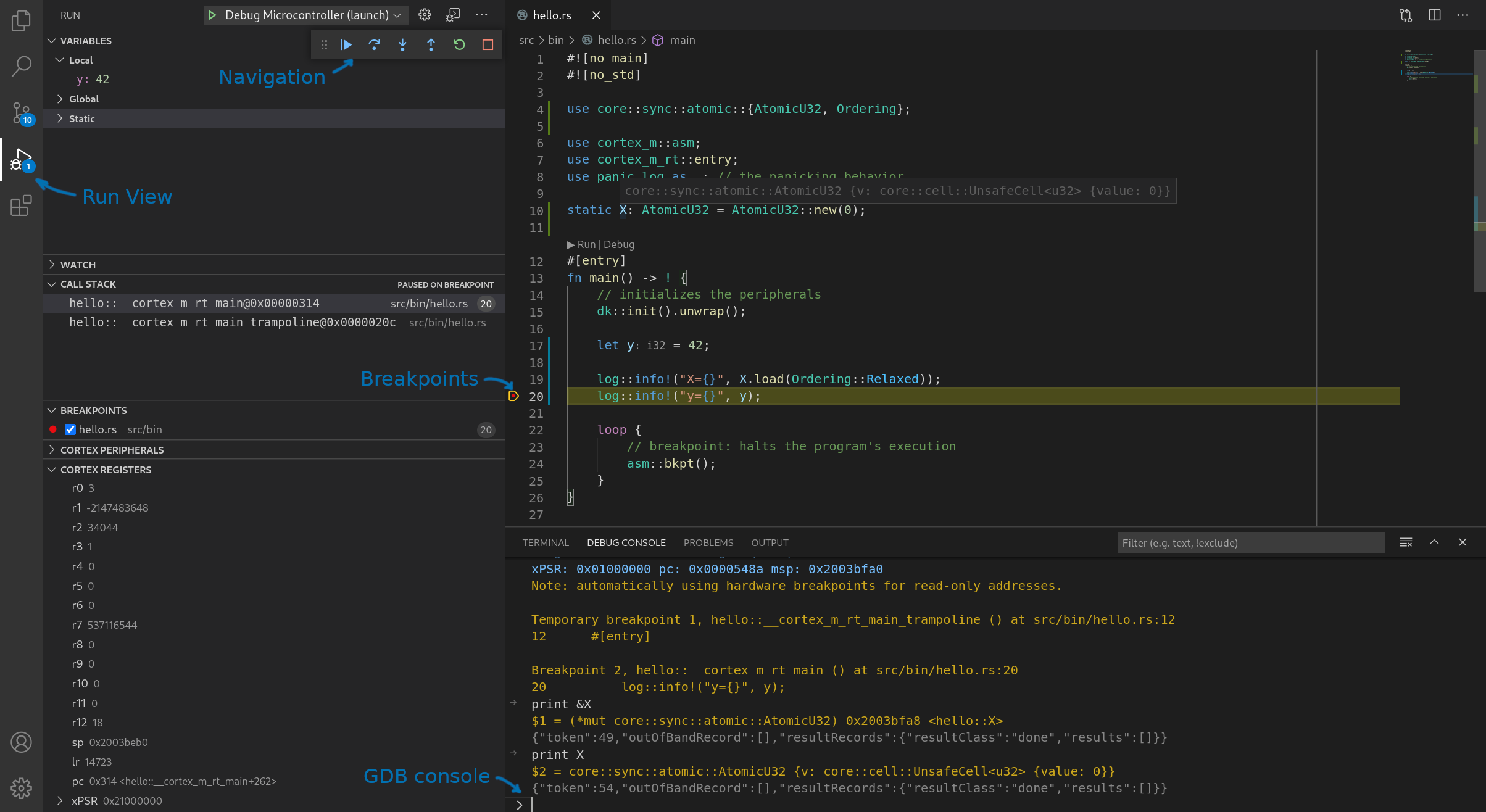
You are now in a GDB session. Switch to the "Run" view (4th icon from the top on the left sidebar), if VS code didn't automatically switch to it, and you'll see debug information like the call stack, local variables, breakpoints and CPU registers on the left side. On the bottom panel, you can switch to the "Debug console" to issue commands to the GDB server. Near the top of the GUI you'll find a row of buttons to navigate through the program (step, continue, etc.). Breakpoints can be added by clicking to the left of line numbers in the file view.
Debugging a different program
To debug a different program within the beginner/apps folder you'll need to modify the
beginner/apps/.vscode/launch.json file as follows:
 {
     "version": "0.2.0",
     "configurations": [
       {
         "cwd": "${workspaceRoot}",
-        // TODO to debug a different program the app name ("hello") needs to be changed
-        "executable": "./target/thumbv7em-none-eabihf/debug/hello",
+        "executable": "./target/thumbv7em-none-eabihf/debug/blinky",
         "name": "Debug Microcontroller (launch)",
Change the name of the program from hello to whichever program you wish to debug.